7
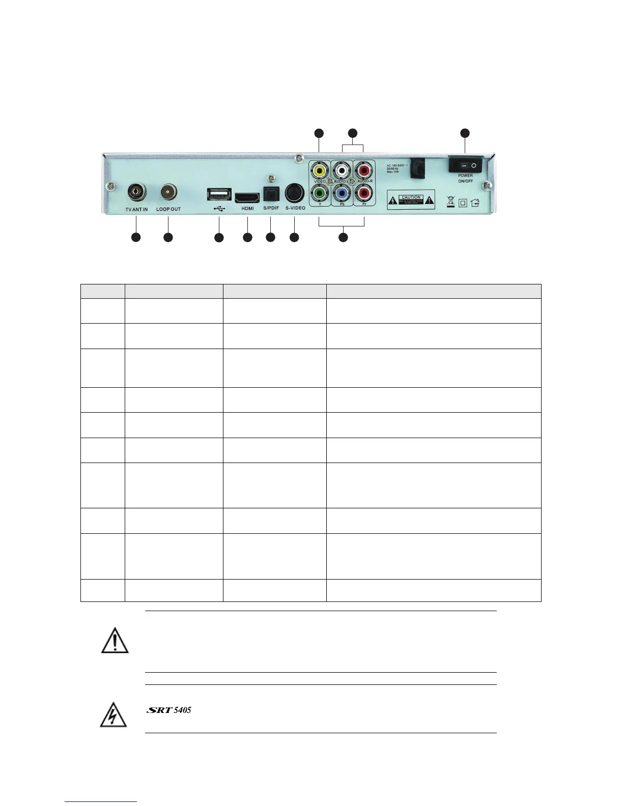
Rear panel
1
3
4
10
2
7
8
9
6
5
No. Name Connector Function
1 TV ANT IN IEC 169-24 female Input from terrestrial antenna
2 LOOP OUT IEC 169-24 female Loop-through output to VCR, etc.
3 USB USB 2.0 A-type
cable
Music and software upgrades
4 HDMI HDMI cable HDMI video-and-audio connection
5 S/PDIF Fibre optic Digital audio output (optical)
6 S-Video MINI-DIN S-VHS video output
7 Y/Pb/Pr RCA
Component
RCA cinch
(green/blue/red)
Component connection (Y/Pb/Pr)
8 Video RCA RCA cinch( yellow) Composite video connection
9 Audio (Left and
Right)
RCA cinch
• white: left audio
• red: right audio
Left and right audio for Component or
Composite connection
10 Power switch —
To turn unit on or off
Note the presence of this symbol on the rear panel. This indicates that
important operating and maintenance instructions accompany the
product. These are set out in this manual. It is highly recommended that
you read this manual thoroughly before using the product.
To reduce the risk of electric shock, do not remove any panel of the
. Even when the unit is turned off, voltages may be present within
it that are of sufficient magnitude to constitute a risk of electric shock.