English
2.0 YOUR RECEIVER
2.1 DEFAULT PIN: 1234
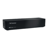
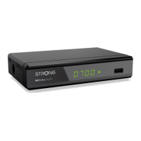
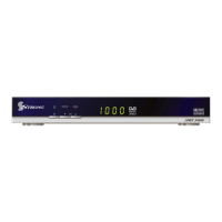
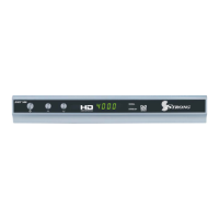
2.2 Front Panel
Fig. 1
1. Mode Indicator LED RED indicates that the receiver is in STANDBY mode.
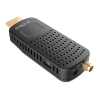
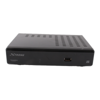
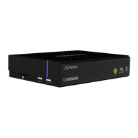
2.3 Side Panel
Fig. 2
1. USB To connect your USB storage device.
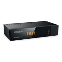
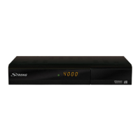
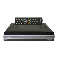
2.4 Rear Panel
Fig. 3
1. IR Sensor Receives commands from the remote control
2. ANT IN To connect to your antenna for reception of broadcast signals.
3. TV SCART To connect your receiver with your TV-set using a SCART cable.
4. S/PDIF Coaxial To connect your receiver to a digital home cinema set, AV receiver
or digital audio amplifier
5. HDMI To connect your receiver with your TV-set using an HDMI cable.
6. ETHERNET To connect to your Ethernet cable (RJ-45) for RSS feeds and
weather forecasts
7. Power cord To connect to the main power (100 - 240 V AC ~ 50/60 Hz)
2.5 Remote control
Fig. 4
1. q Switches the receiver On/Standby.
2. ! Mutes all audio outputs of the receiver
3. 0~9 Enter channel number in TV mode or value input in menu
4. FAV Opens the favourite group selection.
5. 9 One step back in menu or back to previous channel.
6. INFO Opens the current channel information; 2x opens the current
event information and 3x the next event information.*
7. EPG Opens the EPG* (Electronic Programme Guide) in TV mode.
8. pq Change channel to next/previous.
Menu: Moves the cursor up/down.
9. tu Decreases/increases the volume level.
Menu: Change settings for specific menus.
10. OK Opens the current channel list in menu: for confirmation
11. MENU Opens the main menu, in a menu you will get one step back.
12. Exits from the menu or sub-menu.
5