US-29
4-7 Modules/Boards
Replace the respective board in case of malfunction or defect.
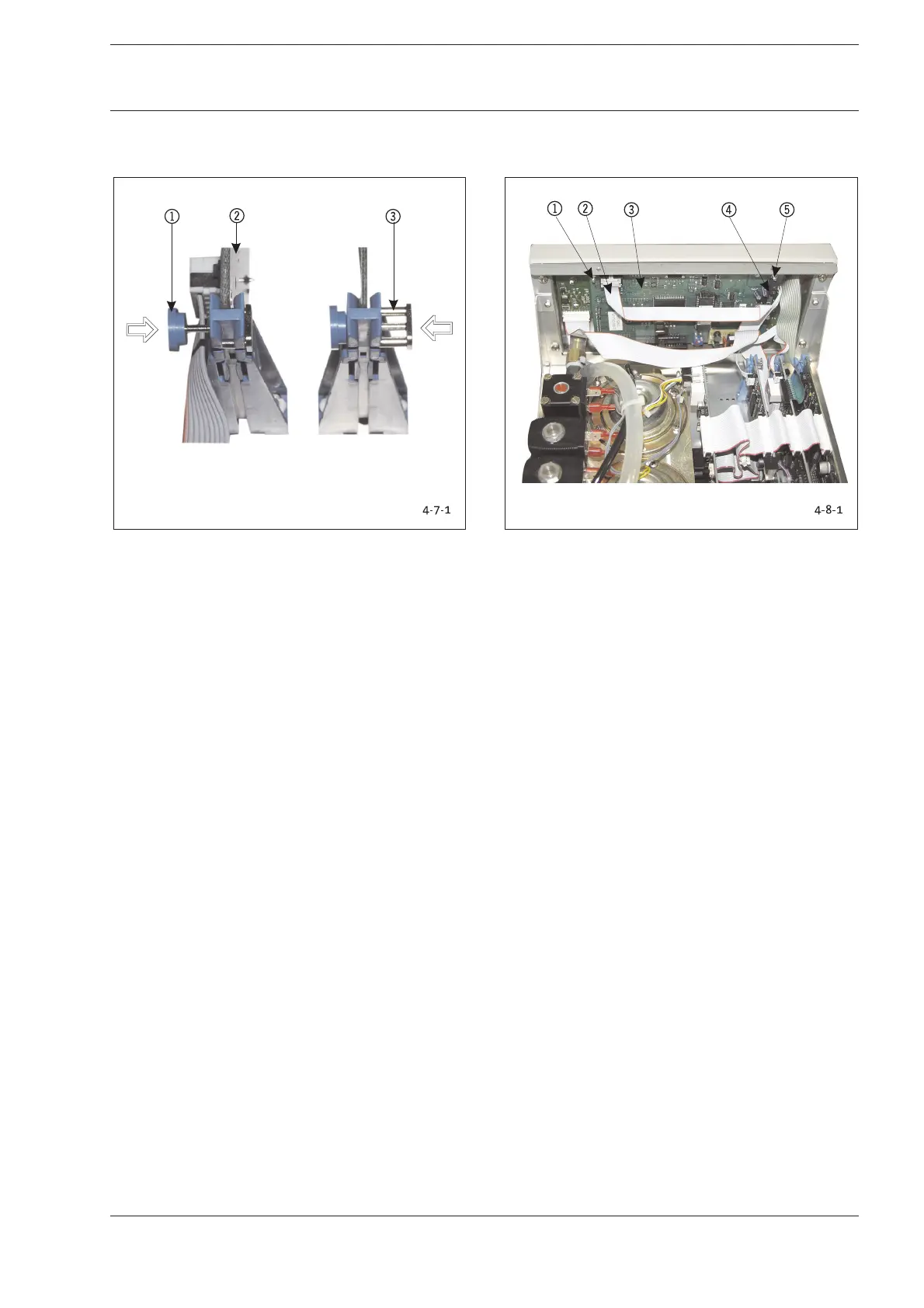
Fig. 4-7-1: Component Boards-/Module Release
1 Locked position-> Press to release
2 Component Board/Module
3 Released position-> Press to lock
1. Remove the electrical plug-in connectors from the
component boards/modules.
2. Firmly grasp component board/module and press button
1to release.
3. Reverse instructions to install elements.
4. Lock component board/module ->Position 1.
Conduct the following test after replacing modules or
components:
Function test of replaced components.
4-8 Video Board/LCD
Replace video board if malfunctioning and in case of defects.
Fig. 4-8-1: Position Video Board/LCD
1 Fastening Nut/Tooth Lock Washer
2 Plug-in Connector from I/O Module
3 Video Module DIU
4 Terminal Screw for Cable from I/O Board
5 Fastening Nut/Tooth Lock Washer
The video board and the LCD can be removed without first
having to disassemble other components. However, access to
the video board is much easier if the front panel has been
removed (see Chapter 4-12).
A SW 5.5 fork wrench/ring wrench and a small screwdriver are
required for the removal of the video board.
Be careful not to damage any cables or other components
when removing the video board.
1. Remove the cable connectors 24.
2. (4x) Unscrew the fastening nuts 15and tooth lock
washers at the corners of the video board 3.
3. Watch out for the distance sleeves between video board
and LCD when removing the video board together with the
LCD from the bolt screws.
Reverse instructions to install elements.
Conduct the following test after replacing modules or
components:
1. Function test of LCD display.
4 Replacing Components
4 Replacing Components