US-30
DE
4-9 Heater Board HB
Replace heater board if malfunctioning or in case of gas heater
tube defects.
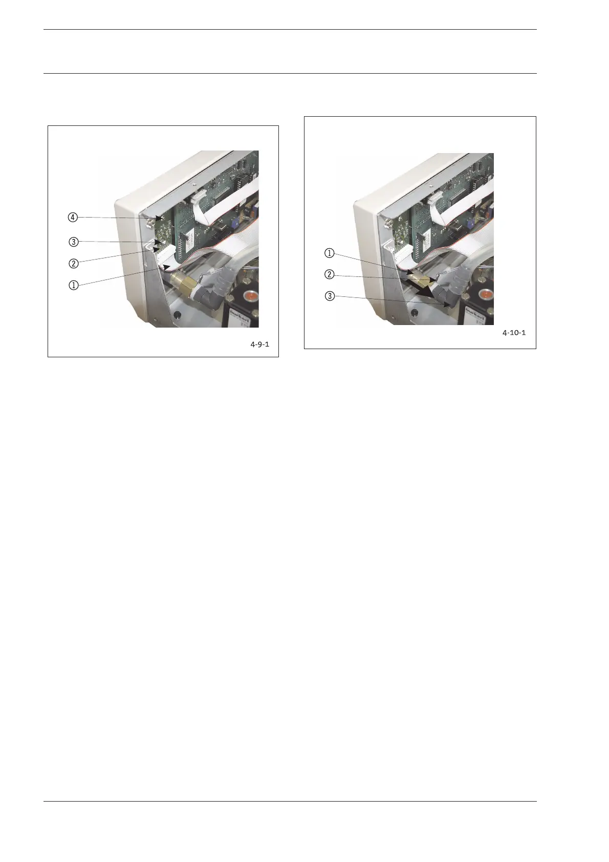
Fig. 4-9-1: Position Heater Board
1Connecting Cable to I/O Module IOM
2 Heater Board HB
3 Nut/Tooth Lock Washer for Fastening
4 Nut/Tooth Lock Washer for Fastening
The heater board can be removed without first having to
disassemble other components.
1. Unscrew fastening nuts and
tooth lock washers 34.
2. Remove board 2together with the connecting cable
1from bolt screws by pulling towards rear.
3. Remove cable connector from heater board.
Reverse instructions to install elements.
Conduct the following test after replacing modules or
components:
1. Heater function test ( Chapter 2-9).
4-10 Insufflation Tube Connection (Gas Outlet)
Replace if surface shows defects that allow leaks.
Fig. 4-10-1: Position Insufflation Tube Connection
1 Fluid Sensor (FLS)
2 Fluid Sensor Electrical Connection
3 L-Shaped Adapter from Fluid Sensor
1 Remove connecting cables and front panel (see Fig. 4-12).
2. Carefully remove the FLS 1together with the L-shaped
adapter 3.
3. Use a SW 19 adjustable wrench to unscrew inner lock nut
from gas outlet.
4. Remove locknut and lock washer.
5. Pull gas outlet towards front and remove.
Reverse instructions to install elements.
Conduct the following tests after replacing modules or
components:
1. Leak test according to Chapter 2-5.
2. Safety test, Chapter 2-1.
4-11 Fluid Sensor
Replace if malfunctioning.
The electrical connector of the fluid sensor
(Fig. 4-10-1, 2) is integrated into the connecting adapter
between insufflation tube connection and pneumatic unit.
If necessary, replace the entire connecting adapter.
1. Remove cable from the cable connector.
2. Detach tube connection as described in Chapter 4-10.
Reverse instructions to install elements.
Conduct the following tests after replacing modules or
components:
1. Leak test according to Chapter 2-5.
2. Safety test according to Chapter 2-1.
4 Replacing Components
4 Replacing Components