US-26
DE
4-2 Gas Connection
The gas connection consists of the following:
Supply-specific connection adapter completely installed
with:
Screw Unions SW 24
O-Ring on Face
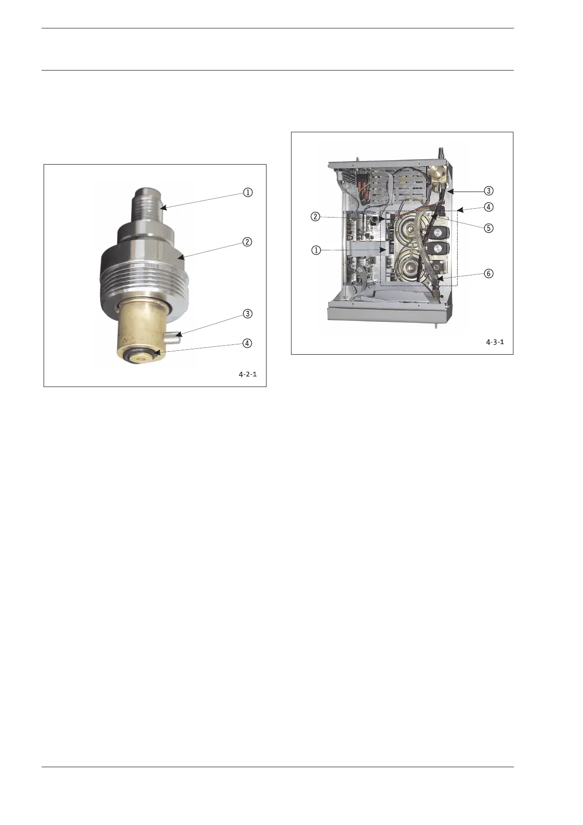
Fig. 4-2-1: CO2 Gas Connection
1 Gas Supply Connection
2 Flat SW 24
3 Anti-Twist Stop
4 O-Ring Seal
Replace elements in case of defective, non-sealing pressure
connections, flow-reducing filter soiling, and if operational
functionality is reduced.
1. Use SW 24 adjustable wrench to Unscrew rear plate
screws.
2. Make sure O-ring remains in place when removing
component.
3. Reverse instructions to install elements. Make sure anti-
twist stop is properly inserted when replacing gas
connection!
Conduct the following tests after replacing modules or
components:
1. High pressure level test (Item 2-3).
2. Flow volume test (Chapter 2-6).
4-3 Low Pressure Unit LPU
Replace elements if malfunctioning and in case of flow
limitation.
Fig. 4-3-1: Position LPU
1 Flat Cable/Plug-in Connection
2 Electrical Plug-in Connection with High Pressure Unit
3 Tube Connection with HPU
4 Complete LPU
5 SW 7 Nut / Tooth Lock Washer (4x)
6 Connection Tube
1. Remove the connection tube from the LPU 36.
2. Unscrew the plug-in connections for the electronic plugs
12.
3. Unscrew four fastening nuts 5 at base case of
pneumatics unit; remove the tooth lock washers, and lift
out the entire LPU complete with block, valves, and board.
Reverse instructions to install elements.
Conduct the following tests after replacing modules or
components:
1. Calibration according to Chapters 3-2-1 to 3-2-6 and
Chapter 3-2-8.
4 Replacing Components 4 Replacing Components