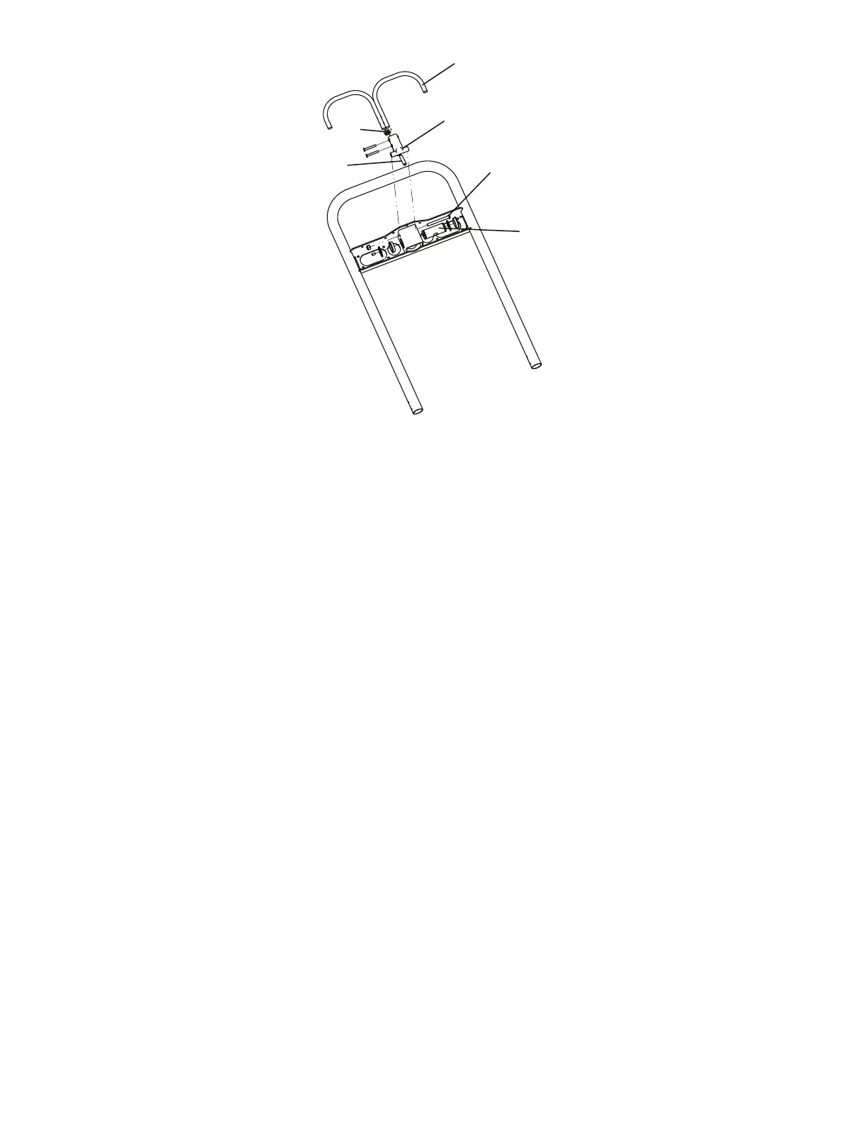
FFiigguurree 33 –– RReemmoovvee tthhee bbaacckkrreesstt ccoommppoonneennttss
4. Lower the backrest to a 5-10 degree angle and release the handle.
5. Apply approximately 50 lb of downward force to the end of the backrest.
NNoottee -- If the backrest drifts downward, turn the set screw counterclockwise. Repeat until the backrest does not drift
downward.
6. Using a 1/2'' combination wrench, tighten the hex nut (F) while holding the set screw fixed in the pivot (Figure 3).
7. Verify proper operation before you return the product to service.
WWhheeeell lloocckkiinngg ffoorrccee aaddjjuussttmmeenntt
TToooollss rreeqquuiirreedd::
• 5/32'' hex wrench
• 7/16'' combination wrench or socket
PPrroocceedduurree::
1. Using the 5/32" hex wrench and 7/16" combination wrench or socket, remove the socket screw from the center of the
lock pedal. Save the screw. The wheel lock is initially assembled with the pedal set at the minimum locking force. The
marker on the pedal (A) is aligned with the marker on the octagonal sleeve (B) (
Wheel locking force adjustment
(page
12)).
2. Remove the sleeve (B). Rotate the sleeve counterclockwise to increase the pedal locking force and clockwise to
decrease the locking force. Insert the sleeve into the pedal (
Wheel locking force adjustment
(page 12)).
3. Using the 5/32" hex wrench and 7/16" combination wrench or socket, reinstall the socket screw (removed in step 1).
4. Test the pedal locking force and make sure that the pedal holds before you return the product to service.
EN 12 6086-009-002 Rev AB.2