928 Mixing Console
Alignment E 3/23Edition: 07.02.01
3.3.6 CR Monitor unit 1.928.420
Distortion:
• Feed test signal with nominal level (1 kHz, typ. +6 or +10 dBu)
to the left channel of one of the EXT. SOURCE inputs and press
the SOURCE EXT. pushbutton.
• Remove the CR Monitor unit from the console and reconnect
it via bus adapter (optionally available; order no.
1.228.332.00).
• Select the appropriate input with one of the EXT. SOURCE
pushbuttons.
• Set the level control potentiometer fully clockwise (maximum
level), and the BAL potentiometer to its center position.
• Connect the distortion analyzer to the CR MONITOR OUT-
PUT LEFT.
• Adjust with trimmer potentiometer VR4 on the Side Board to
minimum distortion.
• Connect the distortion analyzer to the CR MONITOR OUT-
PUT RIGHT.
• Adjust with trimmer potentiometer VR3 on the Side Board to
minimum distortion.
Level:
• Connect the AF voltmeter to the CR MONITOR OUTPUT LEFT.
• Adjust the measured level with trimmer potentiometer VR2 on
the Side Board to nominal level +10 dB.
• Feed test signal with nominal level (1 kHz, typically +6 or
+10 dBu) into the left channel of one of the EXT. SOURCE in-
puts.
• Select the appropriate input by pressing one of the EXT.
SOURCE pushbuttons.
• Connect the AF voltmeter to the CR MONITOR OUTPUT
RIGHT.
• Adjust the measured level with trimmer potentiometer VR1 on
the Side Board to nominal level +10 dB.
DIM attenuation:
• Connect the AF voltmeter to either of the CR MONITOR OUT-
PUT RIGHT or LEFT and measure the level.
• Press the DIM switch.
• Adjust the measured level with trimmer potentiometer VR8 on
the Main Board to 20 dB below the level measured before
(e.g. if the nominal level is +6 dBu and the level potentiome-
ter is set to maximum, the undimmed output level will then be
+16 dBu. Therefore, adjust to –4 dBu when the DIM button is
pressed).
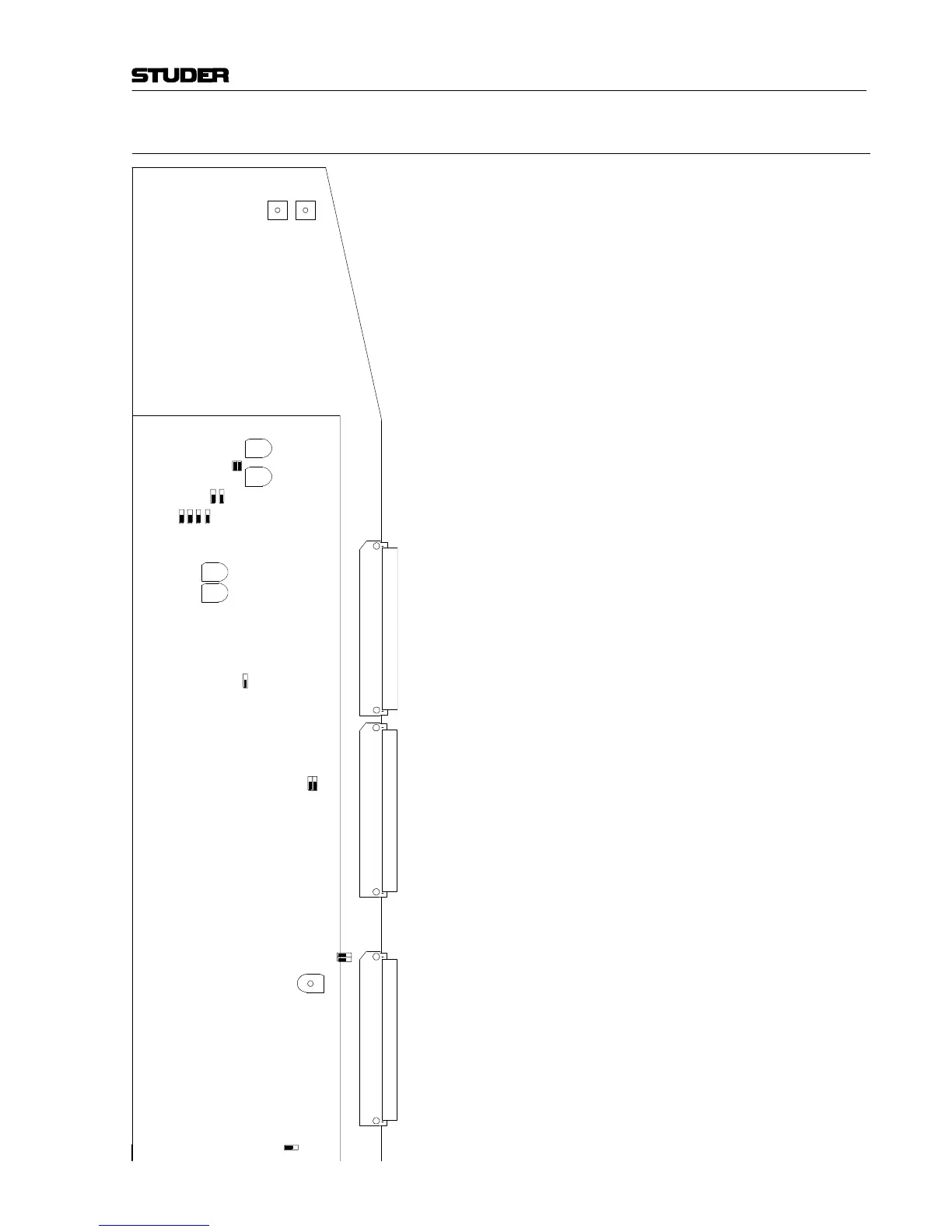
VR8
DIM ADJ
J9
J10
J1
J2
J3
J4
J5
J6
VR6
VR7
FADER 2
ADJ
FADER 1
ADJ
J7
J8
Main Board
1.928.420
(component side)
Side Board
1.928.423
(solder side)
J2
J4
VR3 VR4
VR1 VR2
J3
J1