3.3.7 Studio Monitor unit 1.928.520
Distortion:
• Feed test signal with nominal level (1 kHz, typ. +6 or +10 dBu)
to the left channel of one of the EXT. STUDIO MONITOR in-
puts and press the EXT pushbutton.
• Remove the Studio Monitor unit from the console and recon-
nect it via the bus adapter (optionally available; order no.
1.228.332.00).
• Set the STUDIO level control potentiometer potentiometer ful-
ly clockwise (maximum level).
• Connect the distortion analyzer to the STUDIO MONITOR
OUTPUT LEFT.
• Adjust with trimmer potentiometer VR1 on the Side Board to
minimum distortion.
• Connect the distortion analyzer to the STUDIO MONITOR
OUTPUT RIGHT.
• Adjust with trimmer potentiometer VR3 on the Side Board to
minimum distortion.
Level:
• Connect the AF voltmeter to the STUDIO MONITOR OUT-
PUT LEFT.
• Adjust the measured level with trimmer potentiometer VR2 on
the Side Board to nominal level +10 dB.
• Verify if the right-channel output is within ±0.5 dB from the
left-channel output. The right-channel output cannot be ad-
justed separately.
DIM attenuation:
• Connect the AF voltmeter to one of the STUDIO MONITOR
OUTPUT LEFT or RIGHT, and measure the level.
• Press the DIM switch.
• Adjust the measured level with the trimmer potentiometer VR8
on the Main Board to 20 dB below the level measured before
(for example: if the nominal level is +6 dBu, and the STUDIO
level potentiometer is set to maximum, the undimmed output
level will then be +16 dBu. Therefore, adjust to –4 dBu when
the DIM button is pressed).
Test generator:
• Press the SLATE TO DIR OUT / ~ key in the test generator
section, in order to feed the test generator’s output directly to
the DIRect outputs of all input units.
• Connect the AF voltmeter to the DIR OUT of a mono input
unit.
• Activate the test generator by pressing the TEST GEN ON key.
• Set the TEST GEN LEVEL potentiometer (VR1) fully clockwise
(maximum level) .
• Adjust the measured level with trimmer potentiometer VR7 to
nominal level.
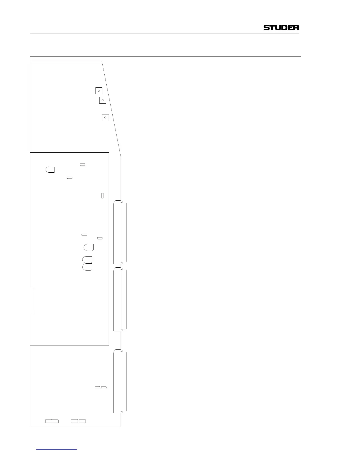
VR7
VR9
VR10
VR11
J1
J2
J5
J6
J7
J3
J4
VR8
VR12
VR13
RA1
VR1
VR2VR3
Main Board
1.928.520
(component side)
Side Board
1.928.520 (solder side)