24 OCH0006F08/13/2024
CEILAIR
®
CW & DX IOM
2.4.3 CONTROLS
There should be at least one equipment-width of clearance around the condenser to ensure adequate airflow
to the coil. Secure the condenser/condensing unit so the system will not move during operation. Refer to
the installation drawing for the non-charged system weight. It is recommended that the remote condenser/
condensing unit be mounted with vibration mounts to reduce the amount of vibration transmitted to the
mounting surface.
2.4.3 Controls
NOTE Locating Controllers
Thermostats and control sensors should not be located near a doorway, a supply air register, or an area
exposed to direct sunlight or external heat sources.
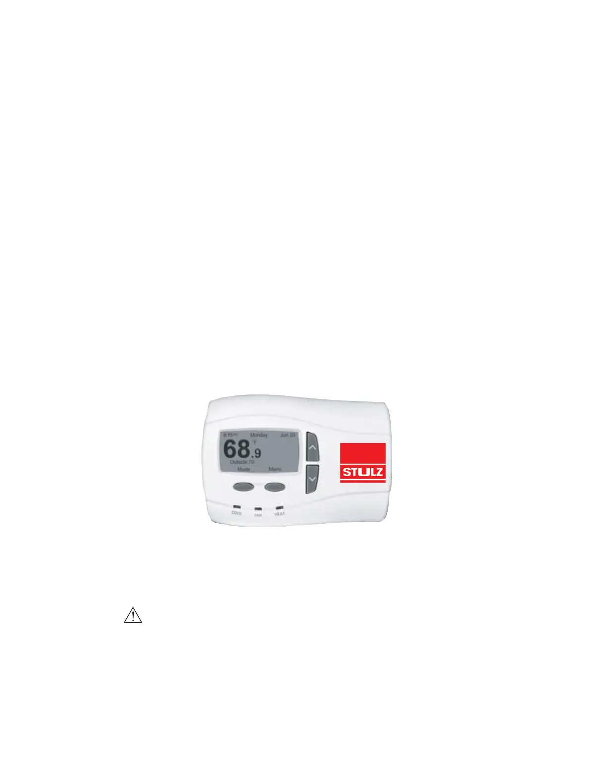
2.4.3.1 ATech Programmable Thermostats
Mount the thermostat upright on an inside wall within the conditioned room at a location that best represents
the average room temperature. In most cases, the thermostat should be located near the common return air
grille. Mount the thermostat at least 18 in from an outside wall and approximately 5 ft above the floor. Follow
the steps below for mounting. Instructions for wiring the thermostat are found in section 2.7.2.
1. Open the case with a flathead screwdriver. Place blade in slot and gently pry forward at the numbered
locations shown in Figure 7.
Figure 7. ATech Controller Installation
2. Place the base temporarily over the wire hole opening in the wall. Level the base and mark the screw
locations through the two provided mounting slots.
CAUTION
Do not touch the temperature sensor on the bottom left corner of the thermostat. The sensor can be
damaged if handled improperly.
3. If using the supplied anchors, drill two 3/16 in holes and tap in the wall anchors. If only the screws are
being used, drill two 3/32 in holes.