38 OCH0006F08/13/2024
CEILAIR
®
CW & DX IOM
2.7 UTILITY CONNECTIONS
2.7 Utility Connections
2.7.1 Main Power
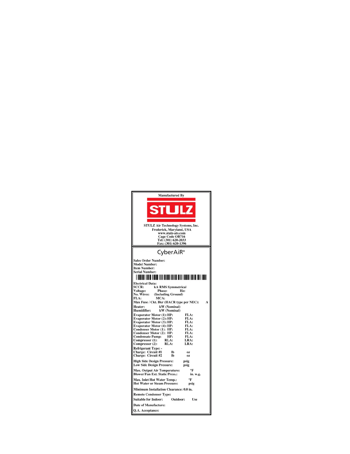
CeilAir units are available in single- or three-phase variations and in a wide range of voltages. Examine the
unit nameplate, located on the outside of the cabinet close to the electric box, to determine the operating
voltage, frequency, and phase of the system (see Figure 15). (Note that the unit serial and model numbers are
also found on the nameplate.) The provided power must meet the listed specifications. The supply voltage
measured at the unit must be within ±10% of the voltage specified on the system nameplate, with the
exceptions noted below.
The nameplate also provides the full load amps (FLA) the unit will draw under full design load, the minimum
circuit ampacity (MCA) for wire sizing, and the maximum fuse size (MAX FUSE) for circuit protection.
NOTE Fuse or Circuit Breaker Requirements
If the nameplate states MAX FUSE/CKT BKR, then fuses or an HACR type circuit breaker are required to
protect the system. Other protection devices are not allowed based upon the product listing.
The unit is provided with terminals for all required field-wiring. Confirm which field connections are required
for the unit options purchased. Refer to the electrical drawings supplied with the unit for more information
about power and control field-wiring.
Figure 15. Sample Nameplate