29OCH0006F08/13/2024
CEILAIR
®
CW & DX IOM
2.4.7 SPOT WATER DETECTOR
5. Route the sensor control cable up to the control terminal block in the electric box and terminate the
control wire. Refer to section 2.7.6.5 and to the wiring diagram supplied with your unit.
6. Seal the hole in the wall behind the sensor.
7. Replace the cover plate on the base.
2.4.6 Humidistat/Dehumidistat (Used with ATech1.1/1.2 Thermostat)
Mounting the humidistat and/or dehumidistat is performed in the same manner as described on page 20.
It should be mounted to a wall within the conditioned room at a location that best represents the average
humidity of the space. In most cases, the humidistat and/or dehumidistat should be located near the common
return air grille. Mount the humidistat and dehumidistat at least 18 in from an outside wall and approximately
5 ft above the floor.
Controls may be installed either on a flush switch box or on a surface switch box. Follow the steps below for
mounting. Instructions for wiring the unit are provided in Figures 1622 and section 2.7.6.2.
1. Pull the dial knob off, loosen the screw (located at bottom of unit), and remove the cover.
2. Make wiring connections according to the wiring diagram provided with your unit.
3. Mount the base with the two #6 screws provided.
4. For external setpoint: reinstall the cover, tighten the screw, and replace the dial knob.
5. For internal setpoint:
a. Turn the dial plate to desired setting and tighten the dial lock screw.
b. Break off the dial shaft at the undercut.
c. Remove the insert from the cover.
d. Remove the protective adhesive backing on the blank insert and press it firmly in place onthe cover.
e. Reinstall the cover assembly and tighten the screw. (If additional security is required an Allen screw
and Allen wrench are provided.)
f. Remove protective cover from face of cover insert.
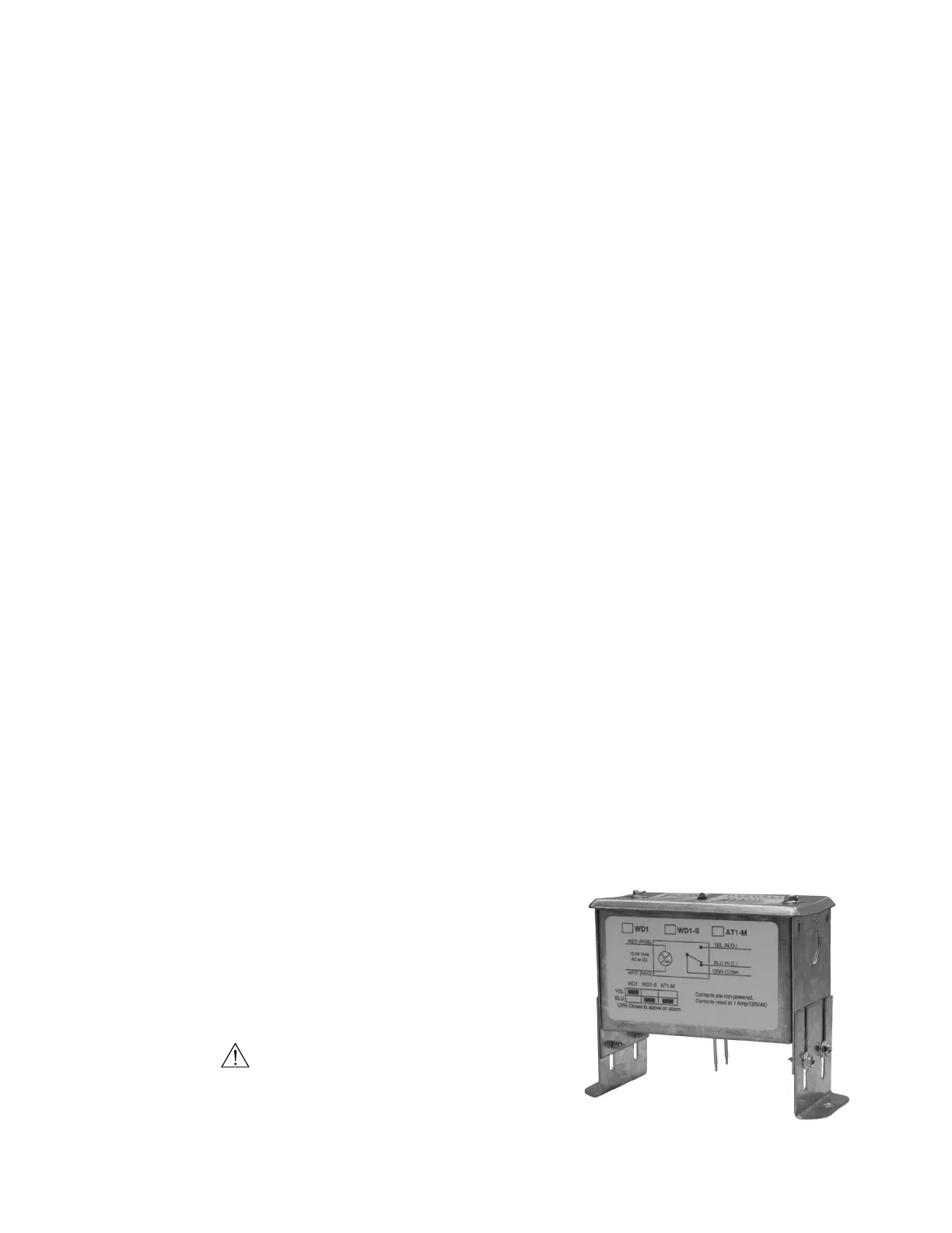
2.4.7 Spot Water Detector
The spot water detector is normally placed on the floor or in a field-supplied auxiliary drain pan located
beneath the unit.
It may be attached using double sided tape or with the mounting
holes provided in the flanges (one on each side). Once it is in place,
loosen the screws provided on the mounting legs to adjust the
height of the sensing probes. When water is present, current will
flow between the two probes.
CAUTION
The probes must not touch the mounting surface. Failure to
adhere to this may result in improper operation of equipment.
Figure 12. Spot Water Detector