28 OCH0006F08/13/2024
CEILAIR
®
CW & DX IOM
2.4.5.2 REMOTE TEMPERATURE/HUMIDITY SENSOR E²
3. Use the sub-base as a template to mark the mounting hole locations on the mounting surface. The drill
size for the wall anchors is 1/4 in. Mount the sub-base over the wires coming out of the wall using the two
screws and anchors provided. Do not use hex head screws.
4. Strip 1/4 in of insulation from the two wires at the remote sensor. Install the wires in the terminals. The
wires can connect with either polarity. Seal the hole in the wall around the cable to eliminate any draft that
might affect the sensor.
5. Make the wiring connections. Refer to section 2.7.6.4 and to the wiring diagram supplied with your unit.
6. Replace the sensor cover.
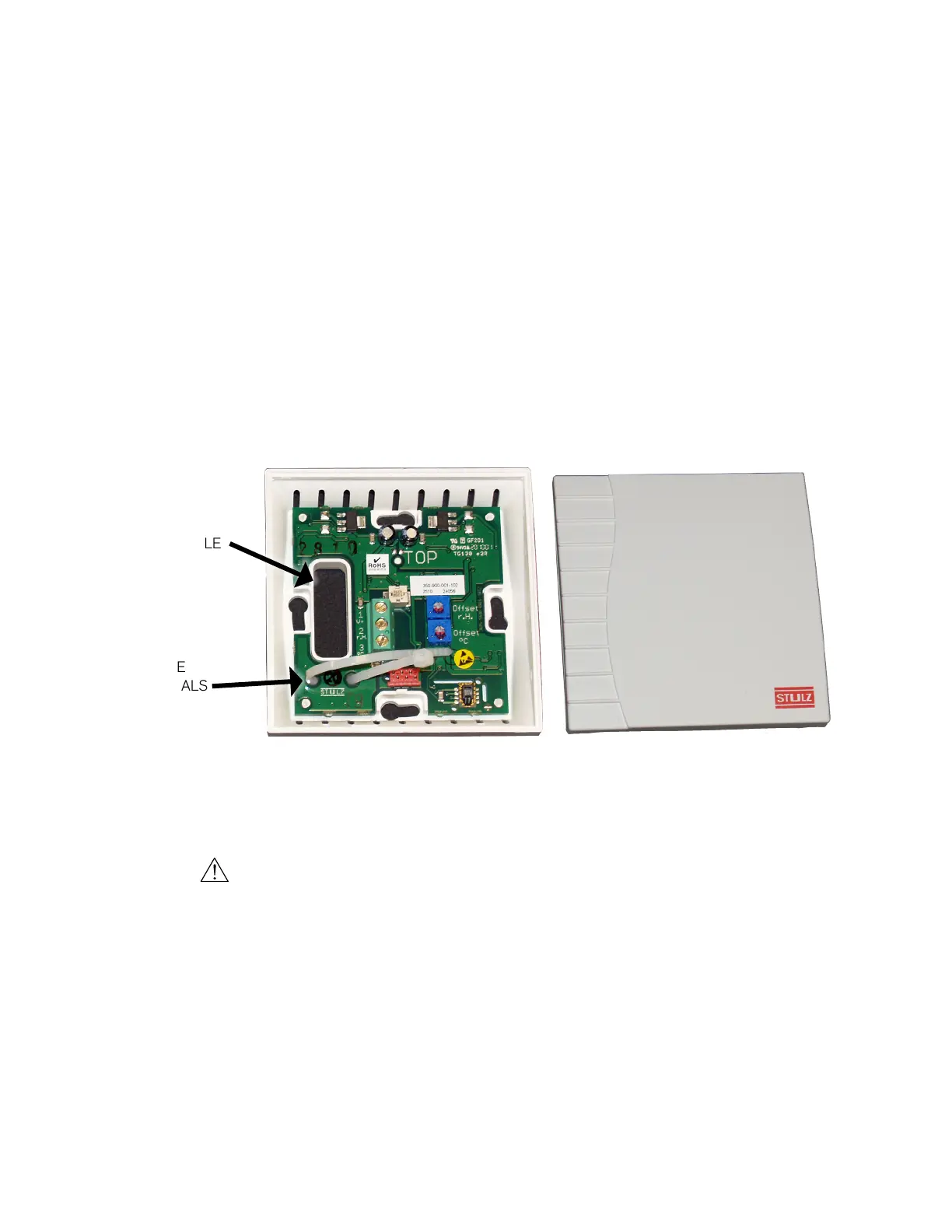
2.4.5.2 Remote Temperature/Humidity Sensor (E²)
OPENING FOR
CONTROL CABLE
WIRE
TERMINALS
Figure 11. Temperature/Humidity Sensor for E
2
Controller
1. Remove the cover from the base of the sensor by squeezing it at the top and bottom.
CAUTION
Take care not to damage the exposed temperature/humidity sensor elements on the PC board when the
cover is removed. The sensor elements can be damaged if handled improperly.
2. Place the base temporarily against the mounting surface.
3. Level the base. Mark and drill mounting holes through at least two of the available slotted holes. Also,
mark through the large opening in the base and drill a hole into the mounting surface for a control cable to
pass through the back of the base.
4. Run a three-conductor shielded cable through the opening in the base, then secure the base with screws,
ensuring the word TOP on the PC board is oriented upward.