41OCH0006F08/13/2024
CEILAIR
®
CW & DX IOM
2.7.2.2 ATECH 1.2 PROGRAMMABLE THERMOSTAT
2.7.2 Controls
STULZ offers a wide range of control systems to meet air conditioning control/alarm requirements. If the unit
is equipped with an ATech controller, see the Honeywell thermostat's User’s Manual online for programming
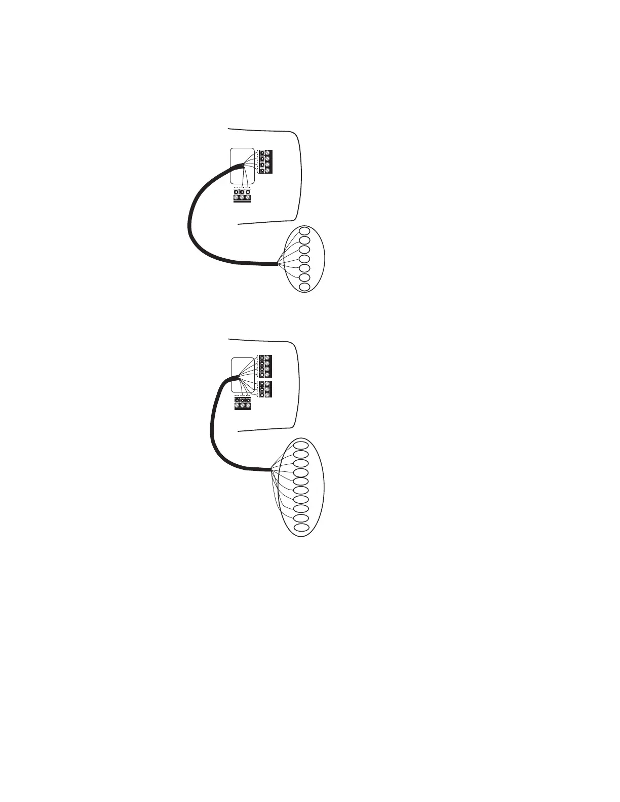
instructions. Wiring contacts on the single- and dual-stage versions of the ATech controller are shown in
Figure 16. If the unit is equipped with an E² controller, see the STULZ E² Series Microprocessor Controller
IOM manual shipped with your unit. For utility connections refer to the appropriate manual above and the
wiring diagram(s) provided with the unit.
The unit is provided with a pilot hole for a conduit connection for control wiring. The hole is located near the
electric box close to the main power pilot hole. The sizing of the conduit must be per the National Electrical
Code and local code requirements.
NOTE National Electric Code Wiring
Customer-provided wiring must be in accordance with the National Electrical Code and local code
requirements for Class 2 circuits.
2.7.2.1 ATech 1.1 Programmable Thermostat
The thermostat requires four conductors wired to the control terminal board located within the unit electric
box. The thermostat has a terminal strip with box type lugs for wire connections. See Figure 16 and refer to
the electrical drawing for proper wire terminations.
2.7.2.2 ATech 1.2 Programmable Thermostat
The thermostat requires seven conductors wired to the control terminal board located within the unit electric
box. The thermostat provides a terminal strip with box type lugs for wire connections. See Figure 16 and refer
to the supplied electrical drawing for proper wire terminations.
Y1
R
C
E/W1
O B G
See OHS Electrical Drawing
for Equivalent Terminal Points
C - 24VAC Common
R - 24VAC
Y1 - 1st stage cooling
E/W1 -
1st stage heating or emergency heat
W2 - 2nd stage heating
Y2 - 2nd stage cooling
L - System fault indicator
O - Cool active reversing valve
B - Heat active reversing valve
G - Fan
TERMINAL DESIGNATORS
W2
Y2
C
R
Y1
E/W1
W2
L
G
B
L
O
Y1
R
C
E/W1
O B G
G
Y1
R
W1
C
B
O
See OHS Electrical Drawing
for Equivalent Terminal Points
A-Tech 1.1 Single-Stage Controller
C - 24VAC Common
R - 24VAC
Y1 - 1st stage cooling
W1 - 1st stage heating
O - Cool active reversing valve
B - Heat active reversing valve
G - Fan
TERMINAL DESIGNATORS
A-Tech 1.2 Two-Stage Controller
Y2
2.7.3 Air-Cooled Split Systems
The system interconnecting field wiring illustrations in Figure 19 through Figure 22 detail the number of
conductors required for a typical system. Additional control conductors may be required depending on the
options purchased with the equipment. Refer to the electrical drawing to determine the total number of
interconnecting conductors required for your system. It is important to note that the control transformer(s)
supplied with the equipment have been sized and selected based upon the expected loads for the system.
Figure 16. ATech 1.1 (top) and 1.2 (bottom) Controller Wiring Contacts