27OCH0006F08/13/2024
CEILAIR
®
CW & DX IOM
2.4.5.1 REMOTE TEMPERATURE SENSOR ATECH
CAUTION
Properly size and vent the P-trap according to applicable codes and best practices.
2.4.4.2 Non-Fused Service Switch
The non-fused service switch may be used to disconnect main power and isolate the unit during maintenance
and service. The switch has a lockable handle to lock power out during maintenance periods. The switch is
typically mounted to the A/C cabinet; however, it may be shipped loose for field installation. The case has a
top keyhole mounting slot and two holes in each bottom corner for mounting. The hardware for mounting the
switch is field supplied. Select suitable fasteners for the intended mounting surface.
The non-fused service switch can be mounted near the unit or in a central location. Non-fused service
switches are rated for either indoor or outdoor use. Ensure that the proper type is used for your application.
NOTE National Electric Code
Refer to the National Electrical Code and local codes for the appropriate mounting location.
2.4.5 Remote Sensors
The remote temperature sensor or temperature/humidity (T/H) sensor must be located so that it will properly
sense the temperature and/or humidity conditions to be controlled. The sensor should not be mounted near a
doorway or an area where it would be exposed to direct sunlight.
When locating the sensor, consider the length of wire to be used. As an option, a 75 ft or 150 ft cable may be
provided by STULZ. Refer to the applicable section that follows to mount the sensor. For wiring details, refer
to section 2.7.2 and to the electrical drawing provided with the unit.
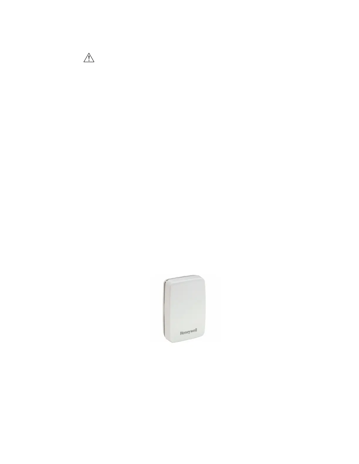
2.4.5.1 Remote Temperature Sensor (ATech)
Figure 10. Temperature Sensor for ATech
NOTE Temperature Sensor Max. Range
The remote temperature sensor has a maximum range of 330 ft.
1. Install shielded or unshielded two-wire twisted cable from the thermostat to the remote sensor location.
2. Open the sensor case by grasping the side and pulling the two halves apart.