31OCH0006F08/13/2024
CEILAIR
®
CW & DX IOM
2.6.1.2 SPLIT SYSTEMS
2.6 Piping Connections
2.6.1 Refrigerant
2.6.1.1 Self-Contained Systems
No refrigeration connections are required for self-contained air, water, or glycol-cooled systems, like models
OHS012/040AS, OHS012/120C, OHS012/120W, and OHS012/120G.
2.6.1.2 Split Systems
Split air-cooled systems will require field refrigeration piping. All split systems are shipped with a dry nitrogen
charge of 100 psig. Systems utilizing a remote condenser will require a copper liquid line and discharge line
(see section 2.6.1.3). Systems utilizing a remote condensing unit (RCU) will require a copper liquid line and
suction line (see section 2.6.1.4).
All refrigeration piping should be installed with high temperature brazed joints. Use standard refrigeration
practices for piping supports, leak testing, dehydration, and charging of the refrigeration circuits. The
refrigerant piping should be isolated with vibration isolating supports. Provide supports—clamps or
hangers —as necessary every 5 to 10 ft of pipe to minimize vibration and noise. To reduce vibration
transmission and prevent pipe damage, use a soft flexible material to pack around the piping when sealing
openings in walls.
Copper conducts heat well. Wrap wet rags around the pipes between the areas to be soldered and nearby
refrigeration components to keep excessive heat from conducting through the pipe and causing damage.
Clear all pipe connections of debris and prep connections for soldering. Use only “L” or “K” grade refrigerant
copper piping. Be careful not to allow solder or piping debris to get inside refrigerant lines. Silver solder
containing a minimum of 15% silver is recommended. Dry nitrogen should be flowing through the tubing
while soldering at a rate of not less than 12 CFM.
Refrigerant lines for split systems must be sized according to the piping distance between the evaporator
and the condenser/condensing unit. Each valve, fitting, and bend in the refrigerant line must be considered
in this calculation. Pipe sizes are given for “equivalent feet,” not linear feet. Do not confuse the terminologies.
For example, a 7/8 in standard 90° elbow has an equivalent length of 1.5 ft; a 7/8 in branch Tee has an
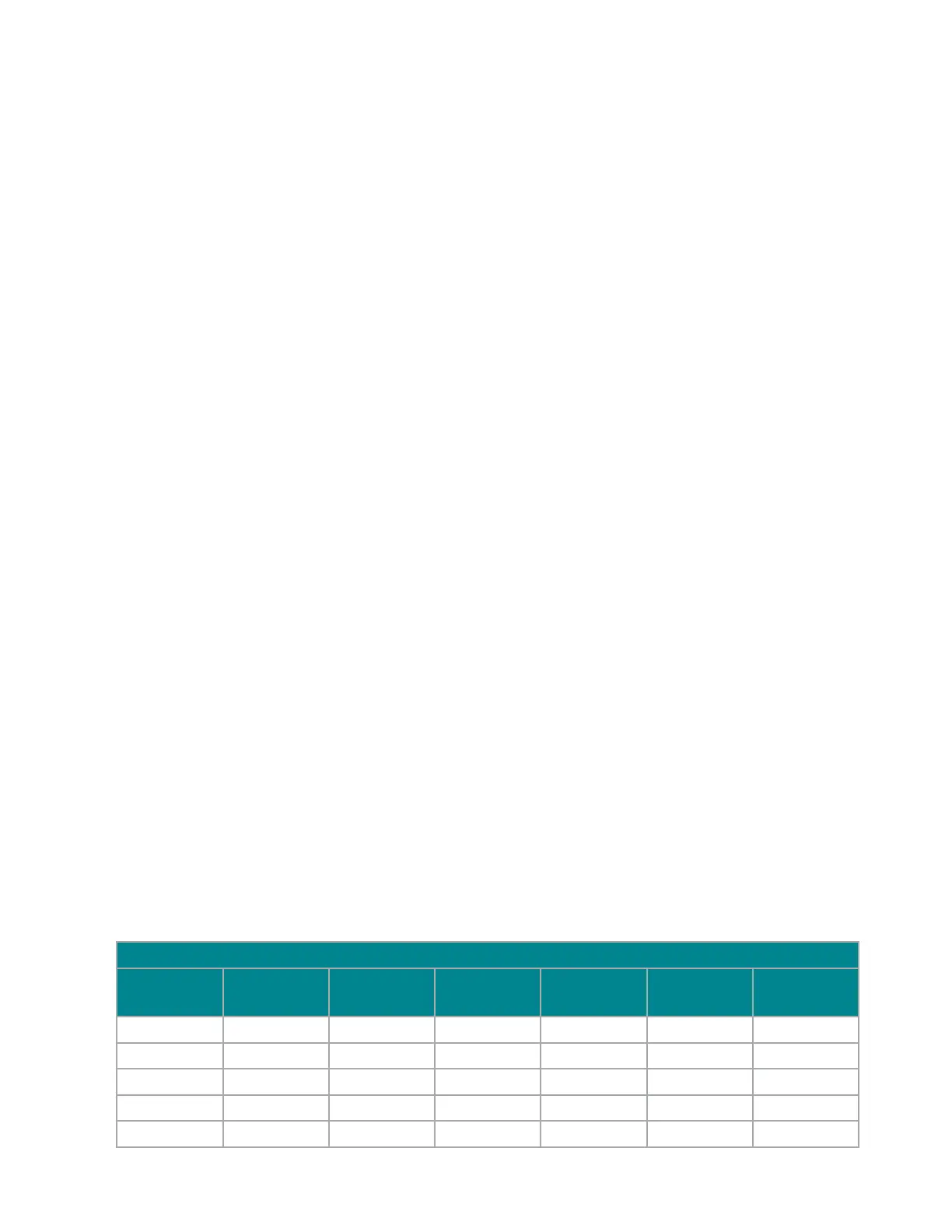
equivalent length of 3.5 ft. These corrections must be accounted for when sizing your piping. Refer to Table 3
for standard equivalent lengths, in feet, of straight pipe.
Table 3. Pipe Equivalent Lengths
Equivalent Length (ft) of Straight Pipe
O.D. (in)
Line Size
Globe Valve Angle Valve 90º Elbow 45º Elbow Tee Line Tee Branch
1/2 9.0 5.0 0.9 0.4 0.6 2.0
5/8 12 6.0 1.0 0.5 0.8 2.5
7/8 15 8.0 1.5 0.7 1.0 3.5
1⅛ 22 12 1.8 0.9 1.5 4.5
1⅜ 28 15 2.4 1.2 1.8 6.0