30 OCH0006F08/13/2024
CEILAIR
®
CW & DX IOM
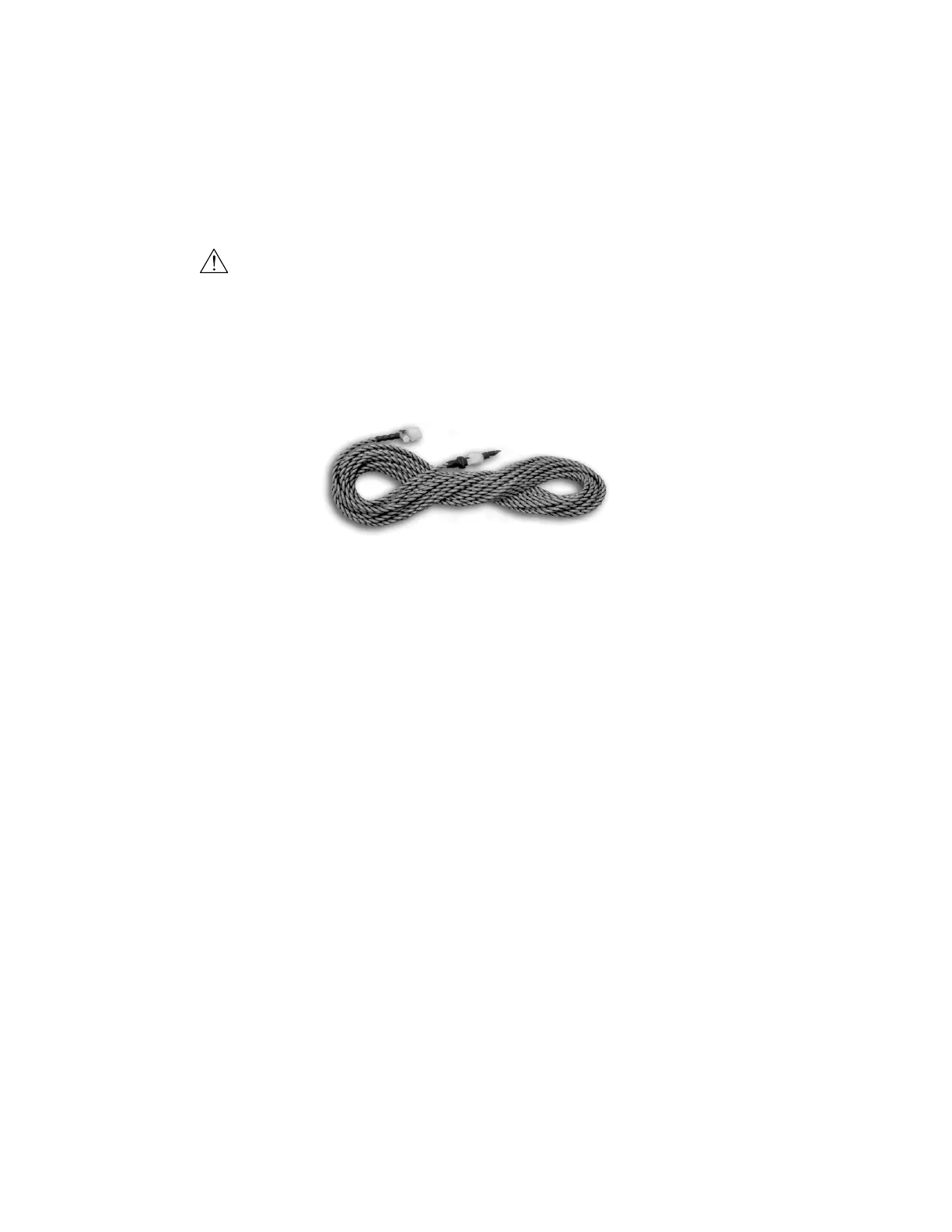
2.4.8 CABLE TYPE WATER DETECTOR
For wiring details, refer to section 2.7.6.3 and to the electrical drawing provided with the unit.
2.4.8 Cable Type Water Detector
CAUTION
Do not allow the cable water detector to contact metal (frame or condensate pan). It must be mounted on
the plastic stand-offs provided with the water detector.
Lay the cable water detector across the surface where water could collect. When water is present, current will
flow between the two wires. A two conductor wire harness is provided with a quick connect fitting on the end.
The harness mates to the fitting on the water detector cable and connects it to the terminal block inside the
electric box.
2.5 Air Distribution Connection
2.5.1 Spot Cooler
For units that are not ducted (see Figure 9), the air conditioner should be mounted above the ceiling grid,
leaving sufficient space for the air grilles to rest on the ceiling T-bar.
NOTE Grille and Gasket Placement
Placement of the grilles is important. The hinged filter grille goes on the return air side of the unit. The
three-way directional grille goes on the conditioned air discharge side of the air conditioner. A gasket
is factory-supplied for the air seal between the bottom flange of the air conditioner and the grille. After
mounting the air conditioner, attach the gasket to the bottom flange, then lower the air conditioner until
the gasket meets the grille, as shown in Figure 8.
2.5.2 Ducted Systems
There are three basic configurations of airflow patterns: 90º/right angle, straight-through and in/out-same-
face (see Figure 9). When determining ducting requirements, always consult your local and state codes.
The duct system should be designed to allow the air to move with as little resistance as possible. Several
factors determine ducting material and size. These factors are predetermined, refer to your ducting system
schematic.
The connection of ducting to the unit is typically accomplished with a 1 in duct flange. Supply air outlet and
return air inlet ducts will require a field-provided duct flange (refer to the installation drawing provided with
the unit). The connection of ductwork to the unit may be made with either pop rivets or self-tapping screws.
Figure 13. Cable Water Detector