13
June 2013
Electrical Systems Operation & Diagnosis Module (602)
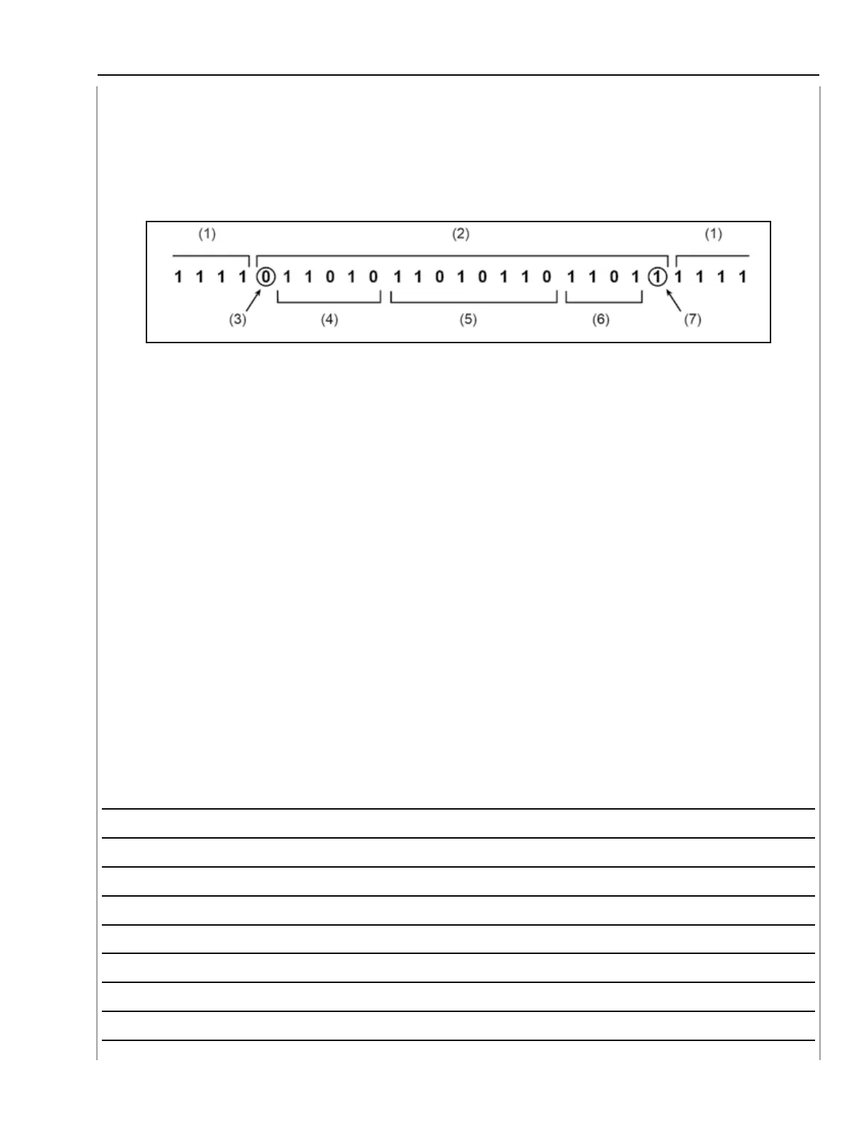
Outline of Data Frame
When data is generated, the signal “Frame” comprises of a “start bit” and a “stop bit” to indicate
the beginning and end of a signal. The frame also includes identification data, main data, and an
error detection code.
Example
Outline of Data Frame Example
(1) Bus idle: Idle state
(2) Frame: Data transmission state
(3) Start bit: Transmission starts
(4) ID bit: It shows what kind of data, for example, TCM, ABS, or ECM.
(5) Data bit: It shows what contents of the data, for example, RPM, shift Position, etc.
(6) Error detection code: It is to avoid wrong recognition of data.
(7) Stop bit: Data transmission stops
“Bus idle” refers to the area between data when no information is being transmitted. At this time,
the data logic value is “1”. Therefore, when the High Speed CAN circuit is 2.5 volts, the system is
at “Bus idle”.,
When a CAN High or CAN Low wire of the High speed CAN carries a transmitted signal, the signal
travels in both directions until the signal reaches the end of the respective wire. At this point the
signal is absorbed by the terminator to the opposite CAN wire.
NOTES:
13