14
June 2013
Electrical Systems Operation & Diagnosis Module (602)
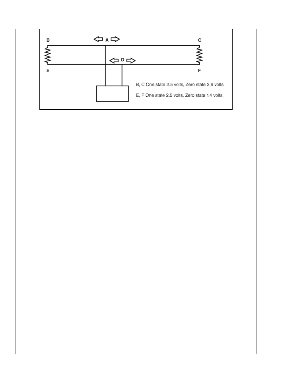
B, C CAN High Wire and E, F CAN Low Wire
For example the CAN High Wire (B, C) receives a voltage signal ranging from 2.5 volts to 3.6 volts.
The signal originates at point A and travels to point B and point C simultaneously.
The potential difference between B, C and E, F during One state is 0 volts but during the Zero
state, the potential difference is 2.2 volts.
During normal operation this potential difference will remain constant.
The voltage output of B, C during the Zero state is actually higher than 3.6 volts but the terminators
allow paths to E, F and 3.6 is the remaining voltage.
The voltage output of EF during the Zero state is actually lower than 1.4 volts but the voltage from
terminators and BC increase the minimum voltage reading to 1.4 volts.
Fail-safe and driveability conditions resulting from problems with the CAN change from year to
year and model to model. These conditions could result in no engine start, limited Electronic
Power Steering operation, non-operative shifter control and many more conditions that control or
monitor normal vehicle operations.
Diagnostics for CAN issues vary as much as the fail-safe and driveability conditions. However;
all High speed CAN circuits share the same circuit structure for the main CAN bus circuit. This
commonality allows the following checks to be performed regardless of model or year of production:
CAN diagnostic checks
1. Resistance
A. Ohm meter
2. Voltage
A. Voltmeter
B. Oscilloscope
3. Communications
A. CAN diagnostic
B. K line
14