15
June 2013
Electrical Systems Operation & Diagnosis Module (602)
High Speed CAN Communication Circuit
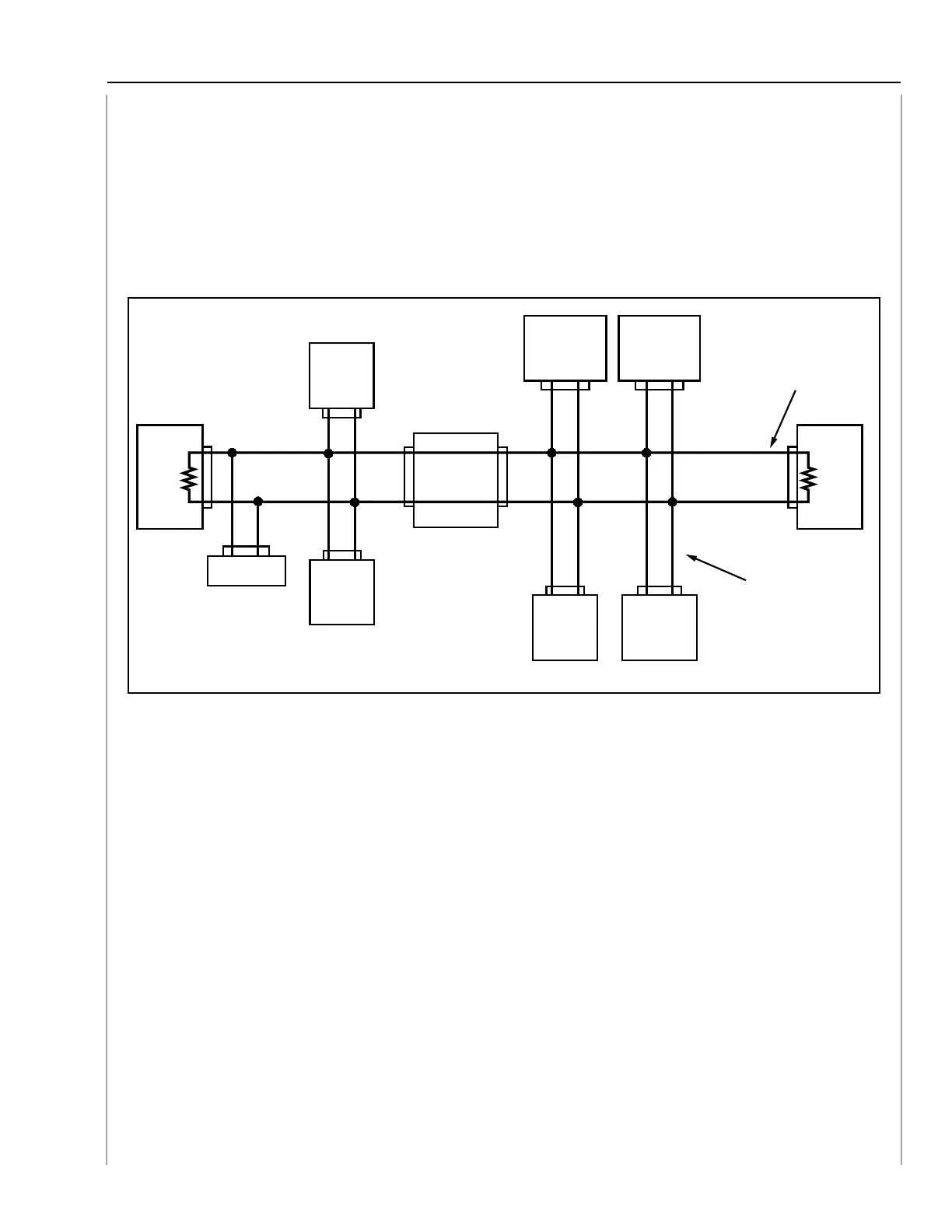
The high speed CAN communication circuit is configured as shown in the illustration.
The communication line connecting the ECM and the VDC is called the main bus, and the
communication lines connecting the main bus and the other control modules are called the branch
buses. Main bus and branch buses are connected by joint connectors.
There is a 120 Ohm resistor in the ECM and VDC CM. They are connected to the circuit as
terminator resistors.
Main bus
Branch bus
ELECTRIC
POWER
STEERING CM
COMBINATION
METER
BODY
INTEGRATED
UNIT
STEERING
ANGLE
SENSOR
VDC CM
120Ω120Ω
TCM
DATA LINK
CONNECTOR
A/C CM
ELECTRONIC
PARKING
BRAKE CM
ECM
High Speed CAN Resistance Check
The DLC is the most accessible connector to measure the resistance of the main bus. If the DLC
is correctly connected to the main bus, the total circuit resistance of the main bus should be 60
ohms. Two 120 ohm resistors wired in parallel provide two paths for the CAN circuit. Since the
resistors have the same value this simple formula determines the total circuit resistance:
RT = V/N RT = 120/2 RT = 60
RT = Resistance total
V = Value of the resistor
N = Number of like resistors
An open, short, or additional resistance added from a malfunction in a control module will affect
the total circuit resistance. This can be measured from the DLC provided no electrical power is
flowing through the CAN.
Note: The total circuit resistance of a parallel circuit is always lower than the
smallest value resistor in the circuit.
15