4. INSTALLATION4. INSTALLATION
Ambient Temperature:
Ambient Humidity:
Altitude:
Atmosphere:
Installation Location:
14°F to 104°F (−10°C to +40°C)
85% or less
3,280 ft (1,000 m) or less
No corrosive or volatile gases, no steam, dust-free, well-ventilated area.
Indoor: Area with minimal dust, not in contact with water.
Outdoors: Unit should be protected from rain and strong winds.
Vibration: Maximum 1G
•
Please consult with factory when the installation conditions deviate from the ones specied above.
•
Drives built to specications such as explosion proof can be used in the specied mounting
environments. However, in regards of the connector to be used on the drive, implement measures
based on the environment.
•
Mount in a location that enables easy operation, such as inspection and maintenance.
•
Mount on a suciently rigid base.
•
Disassembly prevention nuts are installed at 2 locations of the bolt for ring gear housing
(opposing angles) to prevent disassembly of the reducer in case the bolt for ring gear housing
is removed (Figure 4-2). Do not remove the disassembly prevention nuts. Removing them
may result in the anged casing, ring gear housing, internal cover, motor and other parts
disassembling and falling o, and may cause injury.
•
Using only the disassembly prevention nuts with the nut for ring gear housing removed does
not generate a sucient level of torque. Do not use only the disassembly prevention nuts for
ring gear housing for long periods of time, move them excessively or subject them to shock.
Lubricant or grease may leak if there are gaps between any of the mating faces.
•
Tightening the nut for ring gear housing changes the axial force of the disassembly prevention
nuts, and may result in them coming loose. To remove the CYCLO® Drive after temporarily
assembling the device to the driven machine, check that the disassembly prevention nuts have
not become loose.
1. Remove the fan cover if there is one installed (reducer frame size of 6160 or greater).
2. Remove the nut and bolt for ring gear housing. Take care when loosening the nut, as the bolt for ring gear housing
may rotate together.
3. When the device is shipped, dierent size of nut from the one for ring gear housing may be assembled between
nut for ring gear housing and anged casing. Remove this nut, as it is used as a spacer for preventing damage to
the faces of the nut for ring gear housing and anged casing, as well as for covering non-threaded portion of bolt
for ring gear housing.
4. Install the device to the driven machine, and tighten the nut and bolt for ring gear housing with the tightening
torque shown in Table 4-2.
Do not remove the motor’s eye-bolt. In the rare case that it is removed, insert a bolt or other
appropriate material into the screw hole to prevent water or other substances from entering the motor
through the screw hole.
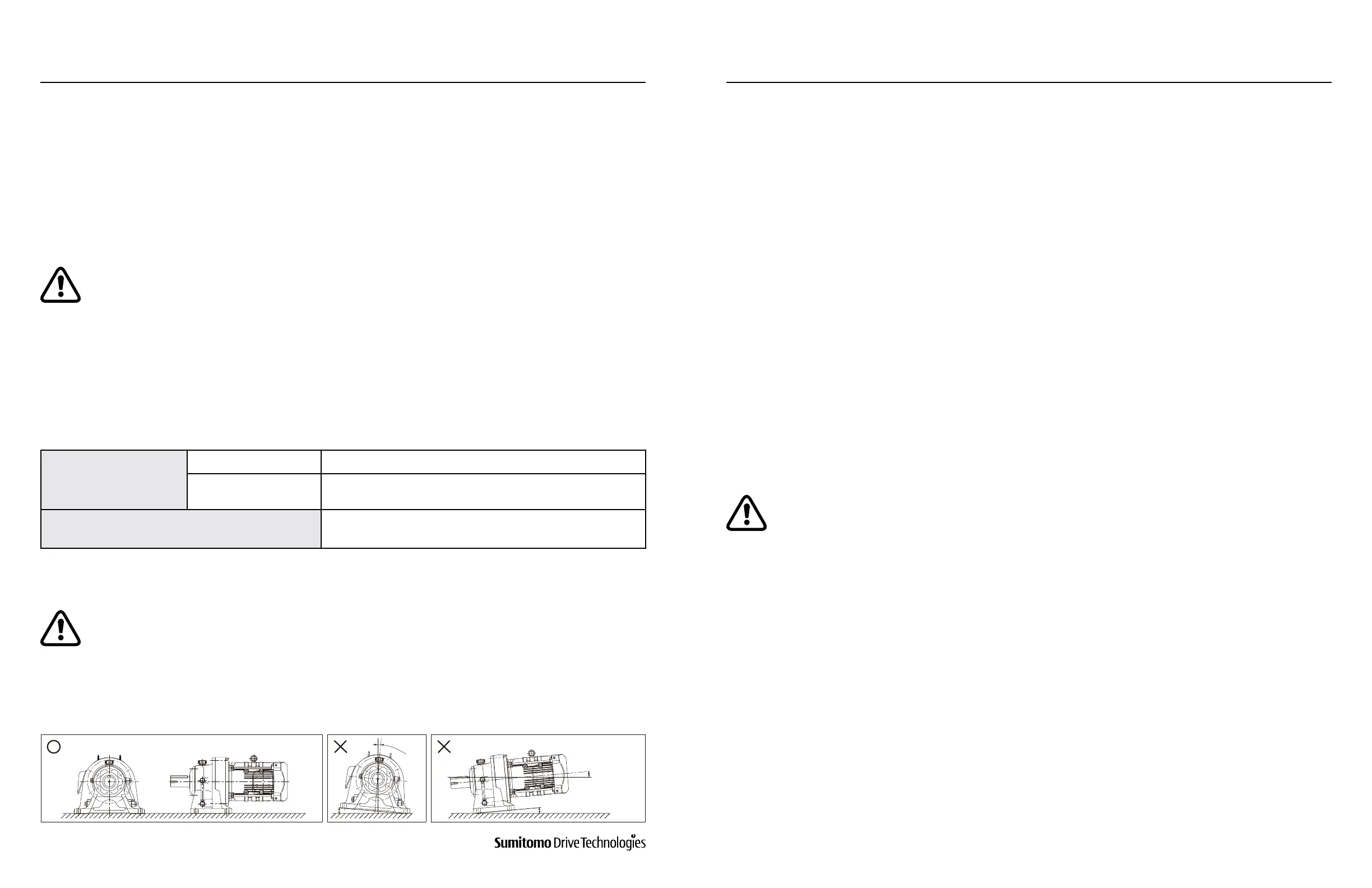
Note: Please consult factory for mounting angles that deviate from the ones specied in Table 4-1.
For units that are built to be mounted in a specic angle, they should not deviate from the specied mounting angle.
Grease Lubricated Units
Maintenance-Free Universal Mounting
Non Maintenance-Free
Depends on nomenclature (horizontal or vertical) as
specied in nameplate.
Oil Lubricated Machines
Depends on nomenclature (horizontal or vertical) as
specied in nameplate.
Table 4-1: Mounting Angle
Figure 4-1: Mounting Angle (Example: Foot Mount Type)
www.SumitomoDrive.com
Cyclo® 6000 Operating and Maintenance Manual
Cyclo® 6000 Cyclo® 6000
Cyclo® 6000 Operating and Maintenance Manual
16 17
4.1 Installation Location
4.2 Mounting Angle
For loading conditions with extreme vibration or frequent starts/stops, it is recommended to use a mounting bolt
class 8.8 (JIS B 1051) or greater. Additionally, a dowel pin should be used in foot mounted units.
For the horizontal slow-speed shaft type (nomenclature starting in CH... or PH...), unit should be mounted as
shown on Figure 4-1.
4.3 Severe Loading Conditions
4.4 Flange Type Assembly Points (Models: CNFM, CHFM,
CNF, CHF, etc.).
1° or more
1° or more