Cyclo® Reducers/Gearmotors are reassembled by reversing the disassembly procedure. Care must be taken to
exclude dust or foreign matter from the moving parts, and to ensure that gaskets are properly placed to make the
assembly oil-tight.
The following procedures and precautions are recommended at time of disassembly and assembly:
The eccentric bearings are specially designed for installation on Cyclo® reducers/gearmotors. They are special roller
bearings without outer raceways (refer to Tables 10-3, 10-4 and 10-5).
It is necessary to insert replacement bearings with numbered surfaces of the inner raceways facing towards the
slow speed shaft. Note: The incorrect insertion of the bearings (i.e., insertion of bearings with numbered surfaces
inside) causes trouble.
1. Set the ring gear housing and insert the ring gear pins and rollers; then test-rotate the pins and rollers by hand. Apply
grease liberally to the ring gear pins and rollers before they are inserted in grease lubricated reducers/gearmotors.
2. Cycloid discs are a matched pair. Each carries the same number stamped on one side of the disc.
3. Set the cycloid disc with the stamped number face up.
4. Insert the spacer (15) and then insert the eccentric with bearings by tapping with a wooden or hard rubber mallet
(See Step 11 of Section 11.1).
5. Insert the other spacer and the inner bearing raceway. Secure them with the retaining ring (See Step 11 of Section
11.1).
6. Set the spacer ring in place.
7. Insert top disc in such a way that the mark is 180° opposed to the mark on the bottom disc.
8. Insert slow speed shaft rollers (See Step 8 of Section 11.1).
9. Put the slow speed shaft pins into the rollers (See Step 7 of Section 11.1).
The above instructions are for eccentric bearings with retainer. Following are the instructions suggested for roller
bearings without retainer:
(a) First insert the eccentric bearing with inner raceways of bearings by tapping with a wooden or hard rubber mallet.
(b) Apply grease to the raceway of the eccentric on the disc. Fix the rollers and set disc in place.
(c) Insert the spacer ring and set second disc in such a way that mark is 180° opposed to mark on the bottom disc.
11.4 Assembly
11.5 Eccentric Bearing Replacement Precautions
Small sizes 6060-6095 have a single disc system, so they dier in construction from larger sizes in the
following ways:
Note: Measure for dimension “X” preferably in 3 places to ensure proper spacing.
1. A balance weight (49) is provided in lieu of the two-disc system.
2. The balance weight must be positioned exactly 180° as opposed to that of the eccentric.
3. There are no end plates on either side of the eccentric. In all other respects, they have exactly the same
construction as the larger sizes. Follow the instructions given under “Disassembly and Assembly”.
1. With casing supported, tap output shaft until it’s disengaged from casing.
2. Remove bearing “A” (7) by using pulling tool.
3. Replace all bearings, gaskets and seals when reassembling.
1. Assemble the “B” bearing (10) on the slow speed shaft (1). Heating of “B” bearing is recommended for easier assembly.
Note: Do not exceed temperature of 200°F (~ 93 °C).
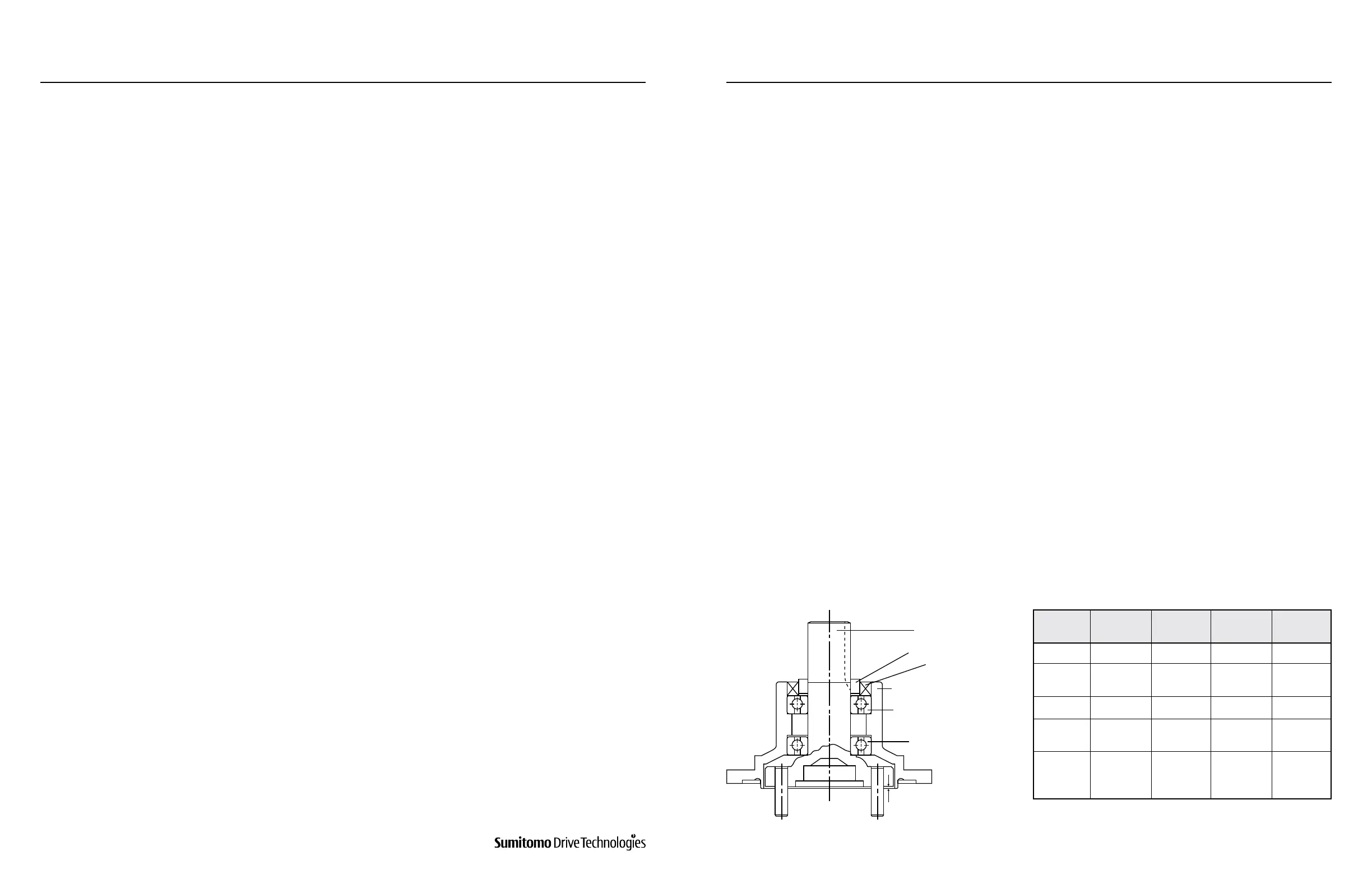
2. Assemble the casing (8 or 39, depending on Cyclo conguration) over the slow speed shaft, being sure to maintain “X”.
3. Carefully tap bearing “A” (7) onto the slow speed shaft until the bearing is ush with the shoulder of the casing.
4. Place the collar (2) onto the slow speed shaft. Heating the collar is recommended for easier assembly.
5. Insert the oil seal (3), lip in, into the casing.
11.6 Disassembly and Assembly of Sizes 6060-6095
Disassembly of Output Side (6060-612H)
Assembly of Output Side (6060-612H)
Figure 11-9: “X” Dimension
Frame
Size
Dimension
(mm)
Tolerance
(mm)
Dimension
(inch)
Tolerance
(inch)
6060, 6065 1.2 ± 0.178 0.046 ± 0.007
6070, 6075
6080, 6085
1.1 ± 0.178 0.042 ± 0.007
6090, 6095 1.2 ± 0.178 0.046 ± 0.007
6100, 6105
610H
1.2 ± 0.178 0.046 ± 0.007
6110, 6115
6120, 6125
612H
1.1 ± 0.178 0.042 ± 0.007
X
10
7
2
1
8 or 39 (Depends on Cyclo
Conguration)
3
Table11-1: “X” Dimension
www.SumitomoDrive.com
Cyclo® 6000 Operating and Maintenance Manual
Cyclo® 6000 Cyclo® 6000
Cyclo® 6000 Operating and Maintenance Manual
90 91
11. CYCLO® ASSEMBLY / DISASSEMBLY 11. CYCLO® ASSEMBLY / DISASSEMBLY