T
7
T
4
T
9
T
7
T
4
T
9
T
6
T
8
T
5
T
6
T
8
T
5
T
1
T
2
T
3
T
1
T
2
T
3
T
4
T
5
T
6
T
4
T
5
T
6
T
7
T
8
T
9
T
7
T
8
T
9
T
1
T
2
T
3
T
1
T
2
T
3
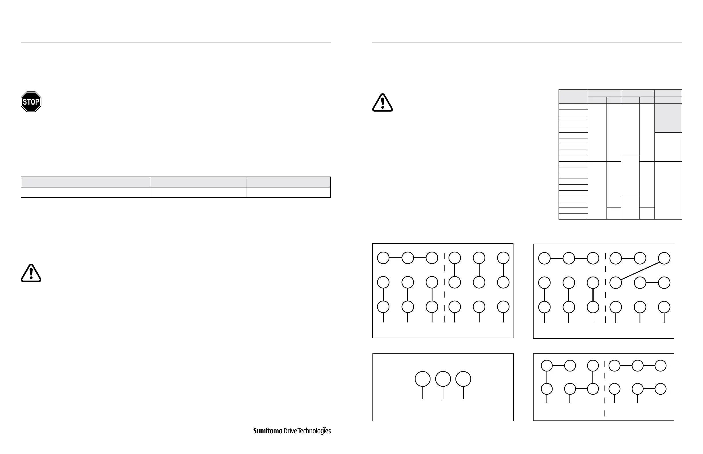
6. MOTOR WIRING
Table 6-1: Insulation Resistance
Figure 6-2: Three-Phase WYE Connection Motor
Figure 6-4: Three-Phase Motor, 575V, 60Hz
Figure 6-3: Three-Phase DELTA connection Motor
Figure 6-5: Single-Phase Motor, 115/230V, 60Hz
Table 6-2: Typical 230/460V, Three-Phase Wiring
Conguration by Motor Type
•
Use a molded case circuit breaker for protection against short circuit.
•
Use an overload protection device that protects the unit against voltage surges.
•
For additional information, please refer to the
motor nameplate.
•
Due to changes in design features, the wiring
diagrams shown in this manual may not always
agree with that on the motor.
Note: In such cases, wiring diagram found inside
the conduit box of the motor should be used.
6.2 Motor Protection
6.3 Motor Wiring Method
1
2
T
1
T
2
T
3
T
3
T
8
T
2
T
3
T
8
T
2
T
1
T
4
T
5
T
1
T
4
T
5
6. MOTOR WIRING
www.SumitomoDrive.com
Cyclo® 6000 Operating and Maintenance Manual
Cyclo® 6000 Cyclo® 6000
Cyclo® 6000 Operating and Maintenance Manual
24 25
Motor Voltage Megohmmeter Voltage
Insulation Resistance
Electric motors of voltage no more than 600V 500V Minimum 1 M(Ω)
When measuring insulation resistance, disconnect the motor from the control panel. Check the motor separately.
A drop in resistance may be attributed to poor insulation. In such case, do not turn on the power. Contact the nearest
Sumitomo representative, distributor, or sales oce.
Based on motor power, determine if motor is WYE or DELTA type
(see Table 6-2).
Line 575V 60Hz Line 115V 60Hz
Line 460V 60Hz Line 460V 60HzLine 200/230 V 60Hz Line 200/230 V 60Hz
Line 230V 60Hz
Wire the motor to the power source using the correct wiring
type as shown on Figures 6-2 to 6-5.
6.1 Measuring Insulation Resistance
•
Never touch the terminals when measuring insulation resistance otherwise electrical
shock may occur.
•
Measure the insulation resistance before wiring. Insulation resistance varies according to
the motor voltage, insulation type, coil temperature, humidity, length of operation, test
electrication time, etc.
•
Under most conditions, the insulation resistance exceeds the value shown in this table:
U.S. Standard Motors
Motor HP
(kW) x P
Standard AF-Motor EP.NA-Motor
Non CSA CSA Non CSA CSA UL/CSA/CE
1/8 (0.1) x 4
WYE WYE
WYE
WYE
1/4 (0.2) x 4
1/3 (0.25) x 4
1/2 (0.4) x 4
3/4 (0.55) x 4
1 (0.75) x 4
WYE
1.5 (1.1) x 4
2 (1.5) x 4
3 (2.2) x 4
5 (3.7) x 4
DELTA
7.5 (5.5) x 4
DELTA
DELTA DELTA
DELTA
10 (7.5) x 4
15 (11) x 4
20 (15) x 4
25 (18.5) x 4
30 (22) x 4
40 (30) x 4
50 (37) x 4
60 (60) x 4
- -
75 (56) x 4