•
Conrm the rotation direction before coupling the unit to the driven machine. Incorrect rotation
direction may cause personal injury or damage to the equipment.
•
When operating the product alone (uncoupled), remove the key that is temporarily attached to the
slow speed shaft; otherwise the key could fall o resulting in injury.
•
Cover rotating parts; otherwise, it may result in injury.
•
When loading the unit and the unit is coupled with pulleys, check that the centering, the belt
tension and parallelism of the pulleys are within the specied limits. When the unit is directly
coupled with the driven machine, check that the direct coupling accuracy is within the specied
limits. When a belt is used for coupling the unit with the driven machine, check the belt tension.
Correctly tighten bolts on the pulley and coupling before operation; otherwise, it may result injury
or damaged equipment due to misalignment.
5. Coupling to Driven Machine
5.1 Check Direction of Rotation
5. COUPLING TO DRIVEN MACHINE
When wiring is performed as shown on Pages 27 to 30, the motor shaft rotates to the right as seen from the Low
Speed Shaft side. In the following diagrams, arrows show the direction of slow speed shaft rotation in this case.
Gear unit construction Single and Triple Reduction Double Reduction
Slow speed shaft rotation
direction (seen from Low
Speed Shaft side)
Table 5-1: Slow Speed Shaft Rotation Direction (Gearmotor)
•
When mounting a connector to the unit, do not apply impact or excessive radial and/or axial load to the shaft.
The bearing could be damaged, or the collar could come o.
•
Interference t is recommended for slow-speed shafts.
5.2 Mounting Connector
5. COUPLING TO DRIVEN MACHINE
Table 5-2: Slow Speed Shaft Rotation Direction (Reducer)
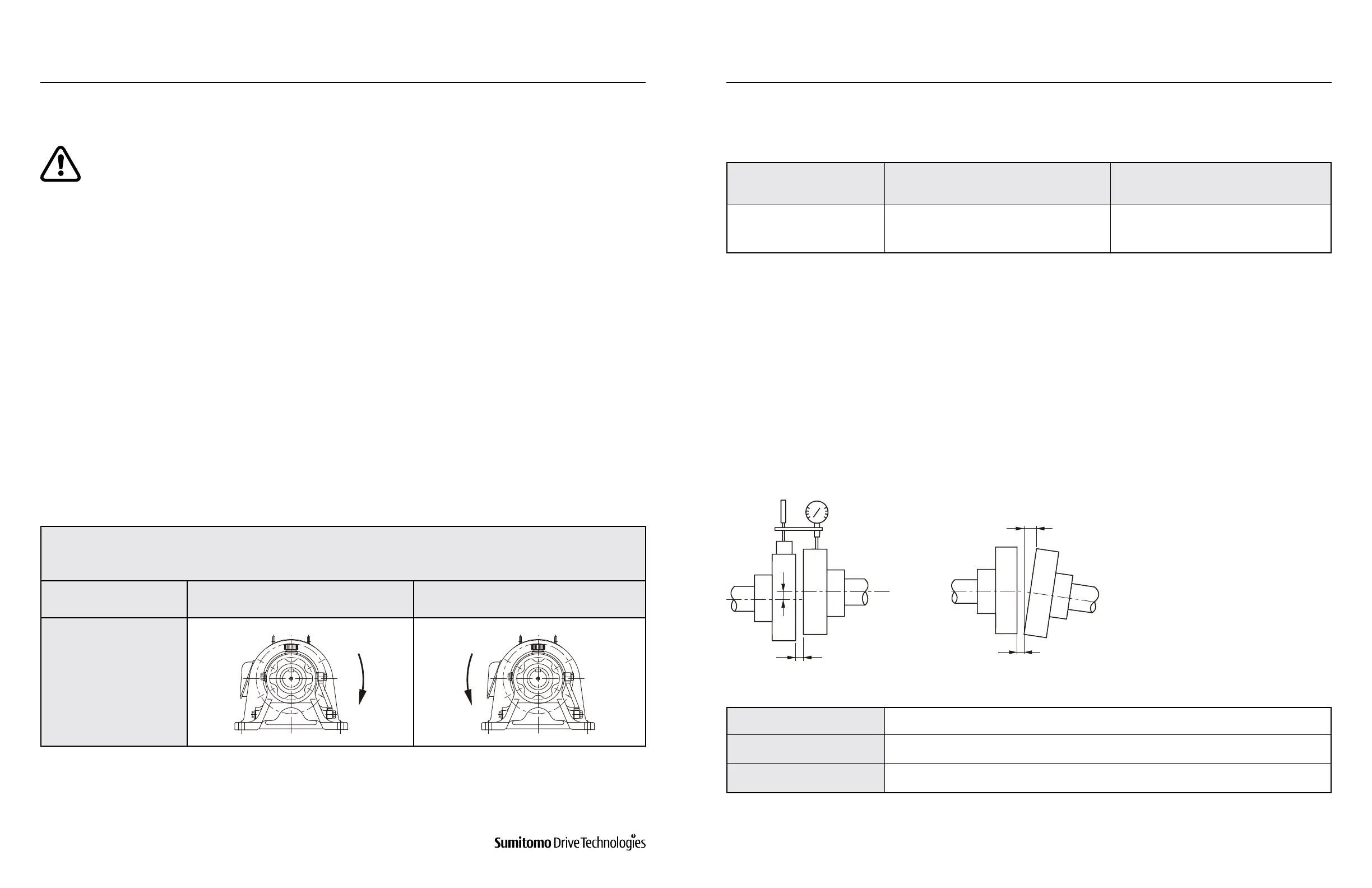
Table 5-3: Alignment Precision for Flexible Coupling
Gear Unit Construction Single Reduction – Triple Reduction Double Reduction
Slow speed shaft rotation
direction
Rotates in opposite direction as the high
speed shaft.
Rotates in same direction as the high
speed shaft.
Allowable Tolerance A 0.1 mm or Manufacturer-Specied Value
Allowable Tolerance B 0.1 mm or Manufacturer-Specied Value
X Manufacturer-Specied Value
Figure 5-1
A
X
B
The alignment accuracy (A, B, X) in Figure 5-1 should be no greater than that shown in Table 5-3.
For Reducer
(1) When Using a Coupling
www.SumitomoDrive.com
Cyclo® 6000 Operating and Maintenance Manual
Cyclo® 6000 Cyclo® 6000
Cyclo® 6000 Operating and Maintenance Manual
20 21
Table 5-1 Shows the direction of slow speed shaft rotation when wiring is performed as on Pages 27 to 30.
For Gearmotor