www.SumitomoDrive.com
Cyclo® 6000 Operating and Maintenance Manual
Cyclo® 6000 Cyclo® 6000
Cyclo® 6000 Operating and Maintenance Manual
8 9
Reducer Specication
C = Ratios 6:1 and greater (Cyclo® Speed Reducer Product Code)
P = Ratios 3:1 and 5:1 (Cyclo® 6000 Planetary Product Code)
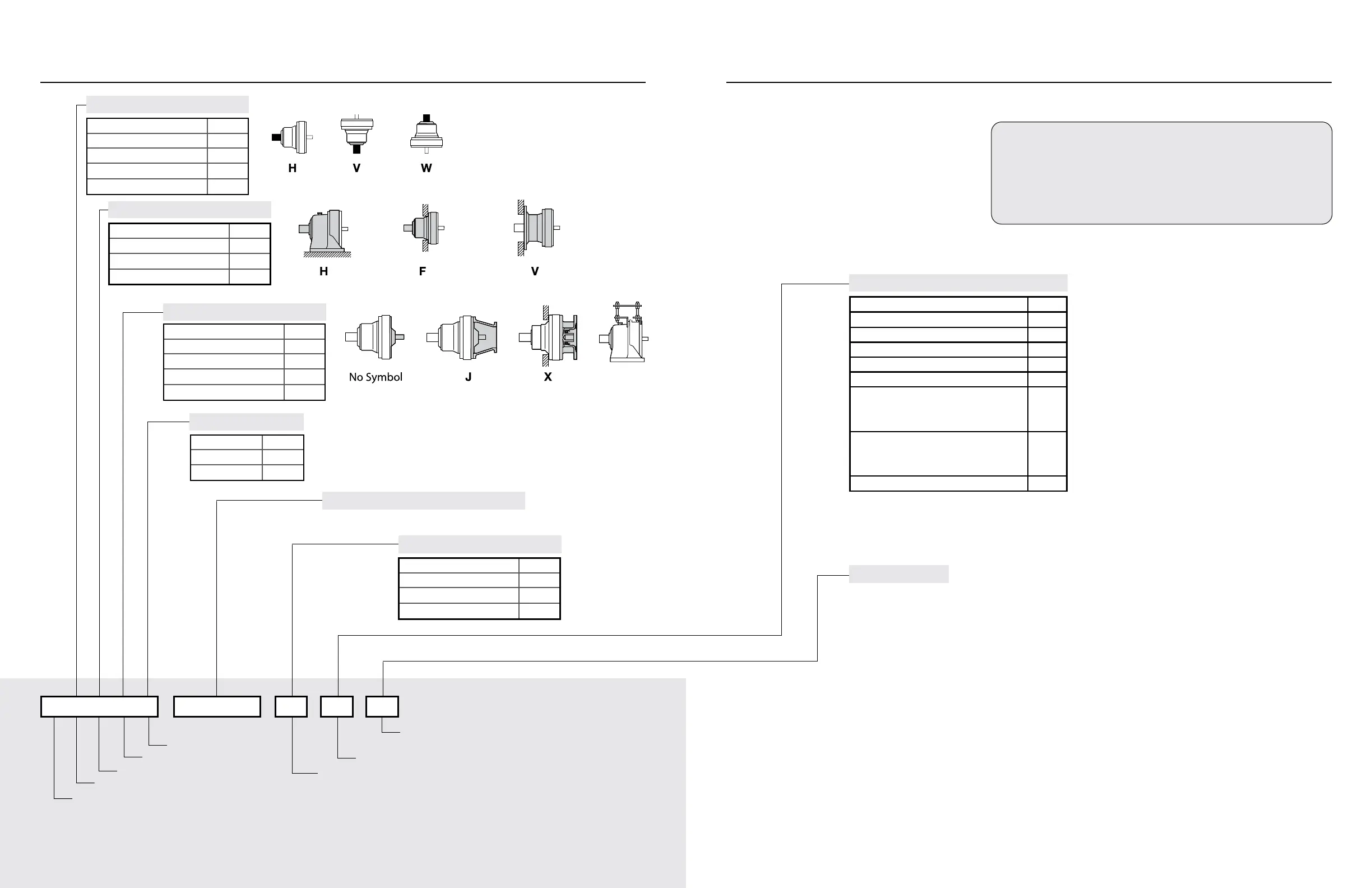
Output Shaft Orientation
Mounting Style
Input Connection
Modication (Special Feature)
Frame Size
Ratio
Shaft Specication
Shaft Specication
Reducer Specication
Nominal Total Ratio
Housing Style
Input Connection
Output Shaft Orientation
Frame Size (Page 10, Table 1-1 to 1-3)
Modication (Special)
Type Code
Foot H
Flange F
V-Flange V
Input Shaft Sux
Inch Y
Metric DIN G
Metric JIS -
Type Code
Horizontal H
Vertical V
Vertical Up (Solid Shaft) W
Universal Direction N
Input Connection Code
None -
C-Face Adapter J
Hollow Input Shaft X
Top Mount P
Code
Special S
Standard -
Example:
CHH – 6165Y – 29
C – Cyclo 6000 6165 – Frame Size
H – Horizontal O/P Y – Inch Shaft
H – Foot Mount 29 – Ratio
Type Sux
Torque Limiter TL
High Capacity Bearing R1
High Capacity Bearings + Ductile Casing R2
Baseplate BP
Shovel Base SB
Top Mount Center -
Right PR
Left PL
HH Type Ceiling H1
Left Wall H2
Right Wall H3
Low Backlash LB
Foot
Reducers With Adapter
V-Flange
Flange
Hollow Shaft Top Mount
P
Foot
V-FlangeFlange
Foot
Reducers With Adapter
V-Flange
Flange
Hollow Shaft Top Mount
P
C H
- - -
H 6 1 6 5
Y 29
C H H
REDUCER NOMENCLATURE1. INSPECTION UPON DELIVERY