•
Do not put ngers or foreign objects into the opening of the products; otherwise, electric shock, injury,
re, or damage to the equipment may result.
•
The products become very hot during operation. Touching the unit may result in burns.
•
Do not loosen the oil ller plug during operation; otherwise, hot, splashing lubricant may cause burns.
•
If any abnormality occurs during operation, stop operation immediately; otherwise, electric shock,
personal injury, or re may result.
•
Do not operate the unit in excess of the load rating; otherwise, personal injury, or damage to the
equipment may result.
•
Is the wiring correct?
•
Is the unit properly coupled with the driven machine?
•
Are mounting bolts tightened rmly?
•
Is the direction of rotation as required?
•
Does the oil level in an oil-lubricated model reach the top red line of the oil gauge when the unit is at rest?
Table 7-1: Items to Check During Operation
Is abnormal
sound or
vibration
generated?
•
Is the housing deformed because the installation surface is not at?
•
Is insucient rigidity of the installation base generating resonance?
•
Is the shaft center aligned with the driven machine?
•
Is the vibration of the driven machine transmitted to the gearmotor or reducer?
Is the surface
temperature
abnormally
high?
•
Is the voltage rise or drop substantial?
•
Is the ambient temperature too high?
•
Does the current owing to the gearmotor exceed the rated current shown on nameplate?
www.SumitomoDrive.com
Cyclo® 6000 Operating and Maintenance Manual
Cyclo® 6000 Cyclo® 6000
Cyclo® 6000 Operating and Maintenance Manual
32 33
7. OPERATION 7. OPERATION
•
Do not approach or touch rotating parts (slow speed shaft, etc.) during operation; otherwise loose
clothing may became caught in these rotating parts and cause serious injury or death.
•
When the power supply is interrupted, be sure to turn o the power switch. Restoration of power may
cause electric shock, personal injury, or damage to the equipment.
•
Do not operate the unit with the terminal box cover removed. Return the terminal box cover to the
original position after maintenance, in order to prevent electric shock.
•
Do not operate the machine while the brake is released by the manual brake release bolt; otherwise,
falling, going out of control, or damage to the equipment may result.
7. Operation
After installation and wiring are completed, check the following items before operation.
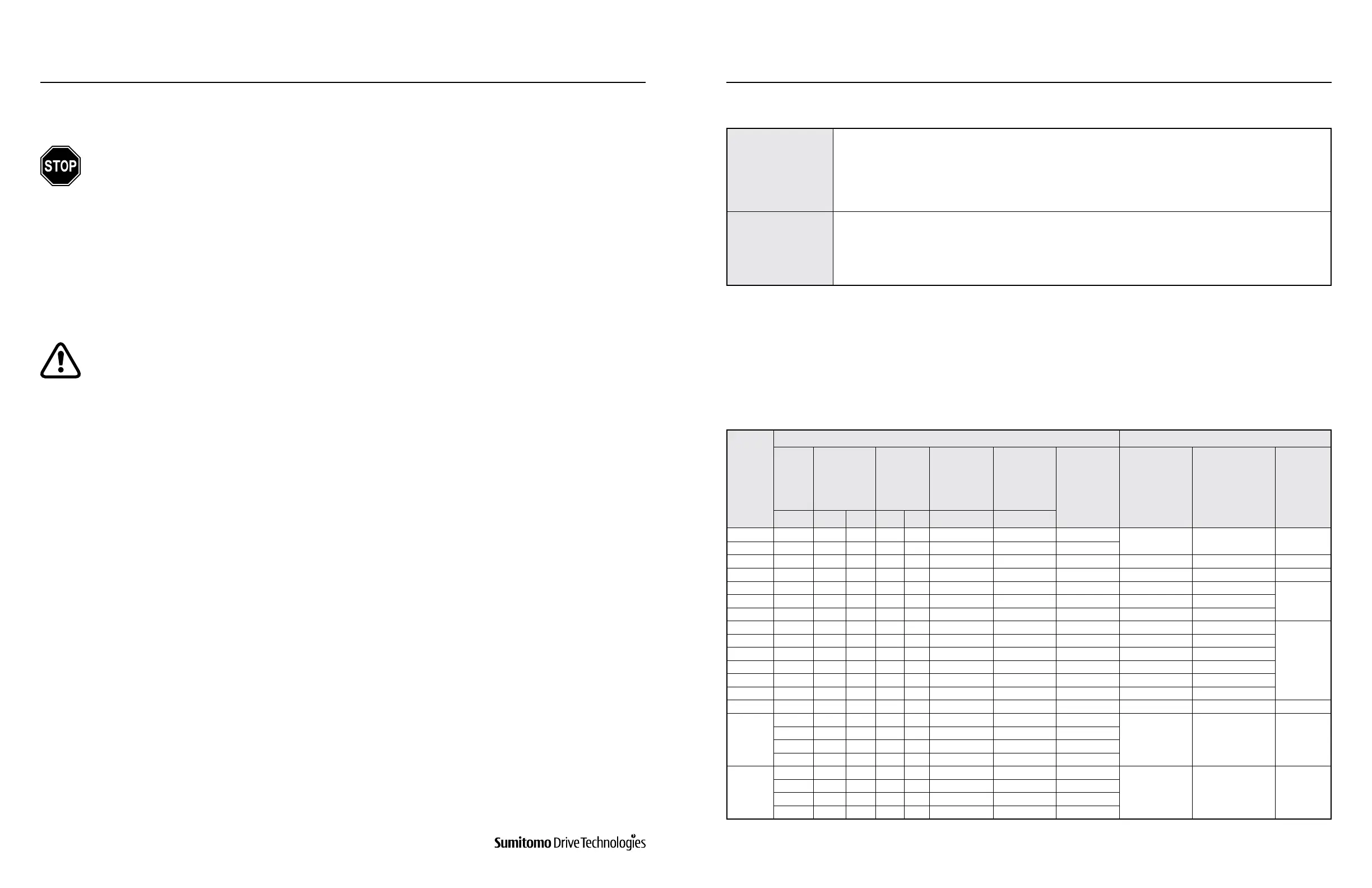
The table below shows standard specication brake types, their brake torque, and their relationship to brake
activation delay time.
If any abnormalities are found, immediately stop operation and contact the nearest authorized service station.
After conrming these items, operate without a load and gradually apply a load. Check the items shown in Table 7-1.
7.1 Items to Check Before Operation
7.2 Brake Torque and Activation Delay Time
Brake
Type
Motor Type Brake Activation Delay Time (sec)
3-Phase
Motor
Premium
Eciency,
3-Phase
Motor
AF Motor
for
Inverter
Premium
Eciency,
3-Phase
Motor
for Inverter
High
Eciency,
3-Phase
Motor
Brake Torque
(Dynamic
Friction
Torque)
(N•m)
Normal Braking
Circuit
(Simultaneous
Turn-O
Circuit)
Normal braking
Circuit for
Inverter
(Simultaneous
Turn-O
Circuit)
Quick
Braking
Circuit
4P 4P 6P 4P 6P 4P 4P
FB-01A1 0.1 - - - - - - 1.0
0.15 – 0.2 0.08 – 0.12 0.015 – 0.02
FB-02A1 0.2 0.25 - - 0.1 - - - 2.0
FB-05A1 0.4 - - 0.2 - - 0.2 4.0 0.1 – 0.15 0.03 – 0.07 0.01 – 0.015
FB-1D 0.55 - - 0.4 - - 0.4 7.5 0.2 – 0.3 0.1 – 0.15 0.01 – 0.02
FB-1E - 0.75 - - - 0.75 - 7.5 0.25 – 0.45 0.15 – 0.25
0.01 – 0.03FB-1HE - 1.1 - - - - - 11 0.45 – 0.65 0.25 – 0.35
FB-2E - 1.5 - - - 1.5 - 15 0.35 – 0.55 0.15 – 0.25
FB-3E - 2.2 - - - 2.2 - 22 0.75 – 0.95 0.4 – 0.5
0.02 – 0.04
FB-4E - 3.0 - - - - - 30 0.65 – 0.85 0.3 – 0.4
FB-5E - 3.7 - - - 3.7 - 40 1.1 – 1.3 0.4 – 0.5
FB-8E - 5.5 - - - 5.5 - 55 1.0 – 1.2 0.3 – 0.4
FB-10E - 7.5 - - - 7.5 - 80 1.8 – 2.0 0.6 – 0.7
FB-15E - 11 - - - 11 - 110 1.6 – 1.8 0.5 – 0.6
FB-20 - 15 - - - 15 - 150 - - 0.06 – 0.14
FB-30
- - 15 - - - - 220
- - 0.03 – 0.11
- 18.5 18.5 - - 18.5 - 190
- 22 22 - - 22 - 220
- 30 - - - 30 - 200
ESB-250
ESB-250-2
- - - 30 18.5 - - 212
- - 0.065
- 37 - 37 22 37 - 266
- 45 30 - 30 45 - 320
- - 37 - - - - 372
Table 7-2: Brake Torque and Activation Delay Time