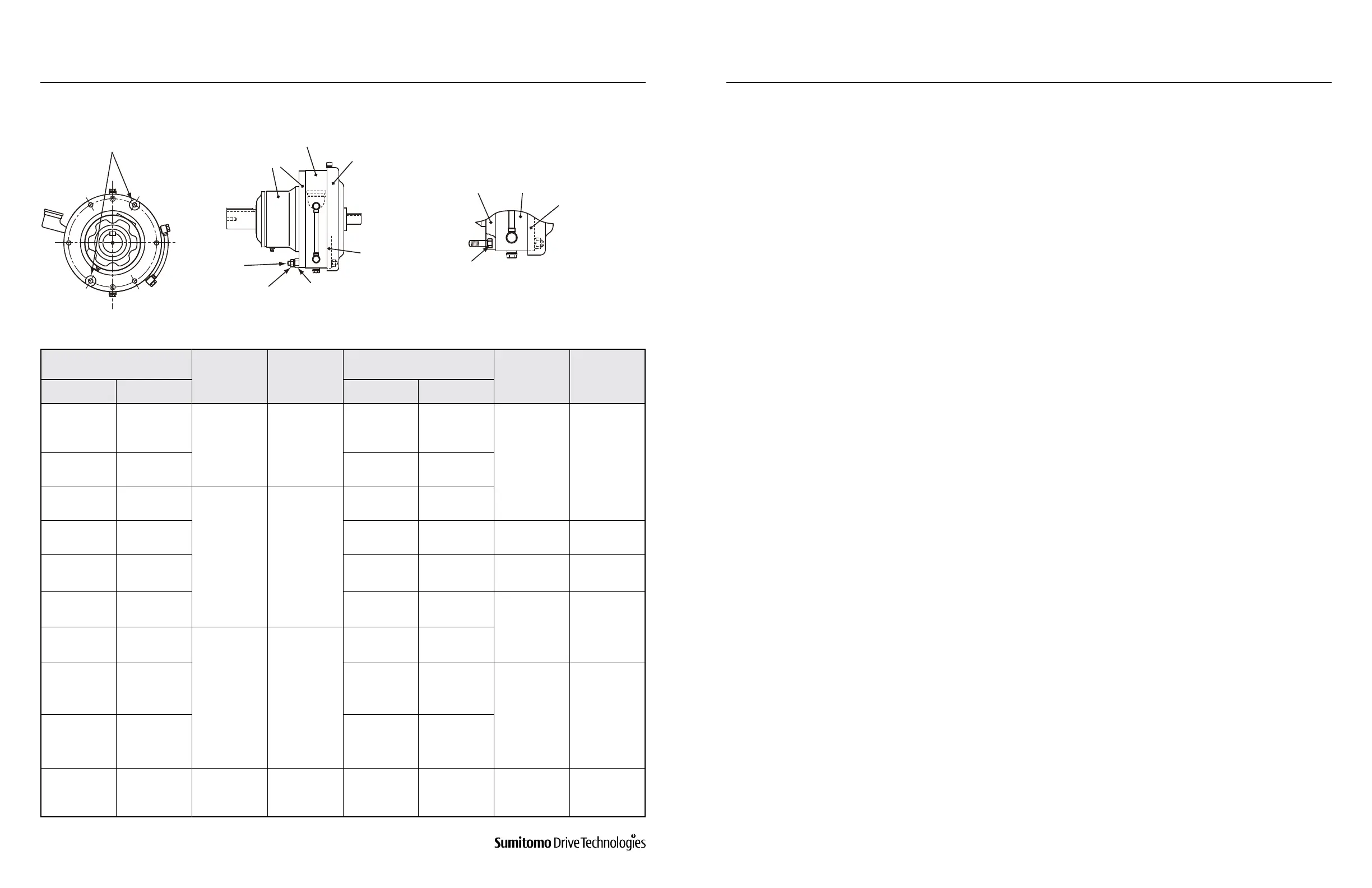
Table 4-2: Torque for Ring Gear Housing Bolts
Figure 4-2
Notes:
1. “X” is for “0” or “5”.
2. If the mounting bolts are changed by the end user, tightening torque that suits the fasteners’ strength should
be used.
3. The position of the disassembly prevention nuts and the shape of each part depend on the frame size.
1. Remove oil, dirt and other contaminants from the motor shaft and Cyclo® hollow high speed shaft. The inner
surface of the high speed shaft is treated with rust prevention oil before shipping.
2. Coat the motor shaft with molybdenum disulde grease to prevent fretting.
3. Align the motor shaft key with the high speed hollow shaft keyway.
4. Depending on the motor combination, a spacer for preventing the key from falling out may be in a separate
shipment. Before assembly, insert the spacer deep into the hole in the high speed shaft. Operation with uninserted
spacer could result in the key falling out and damaging the shaft.
5. When assembling the motor and Cyclo® Drive, make sure that the centers of both shafts are aligned. Do not force
the assembly if the shafts are slanted or misaligned or if the key is only partially engaged.
6. Fasten the motor and adapter plate (internal cover) using the motor mounting bolt. Tighten after conrming that
the motor pilot is in contact with the adapter’s (or adapter’s plate) surface.
Important: If the bolt is tightened the motor pilot surface and adapter’s (or adapter’s plate) are not in contact, this
will result in uneven tightening, causing damage to the internal bearing and other components.
4.5 Motor Mounting on Cyclo® Quill (Hollow) High-Speed
Shaft Option
Internal cover
Flanged casing
Ring gear housing
Disassembly
prevention nuts
(2 locations at opposing angles)
Disassembly prevention nuts
Bolts for ring
gear housing
Nuts for ring
gear housing
Flanged casing
Ring gear housing
Fan cover
Internal cover
Spacer replacement nuts
4. INSTALLATION4. INSTALLATION
www.SumitomoDrive.com
Cyclo® 6000 Operating and Maintenance Manual
Cyclo® 6000 Cyclo® 6000
Cyclo® 6000 Operating and Maintenance Manual
18 19
Frame Size
Size
Tightening
Torque
(N-m)
Frame Size
Size
Tightening
Torque
(N-m)
1 Stage 2 Stages 1 Stage 2 Stages
606X 606XDA
M6 11
617X
617XDA
617XDB
617XDC
M12 96
607X 607XDA 618X
618XDA
618XDB
608X -
M8 25
619X
619XDA
619XDB
609X 609XDA 6205
6205DA
6205DB
M16 219
610X 610XDA 6215
6215DA
6215DB
M18 298
611X - 6225
6225DA
6225DB
M20 475
612X
612XDA
612XDB
M10 55
6235
6235DA
6235DB
613X
613XDA
613XDB
613XDC
6245
6245DA
6245DB
M24 794
614X
614XDA
614XDB
614XDC
6255
6255DA
6255DB
616X
616XDA
616XDB
616XDC
M12 96 6265 6265DA M30 1590