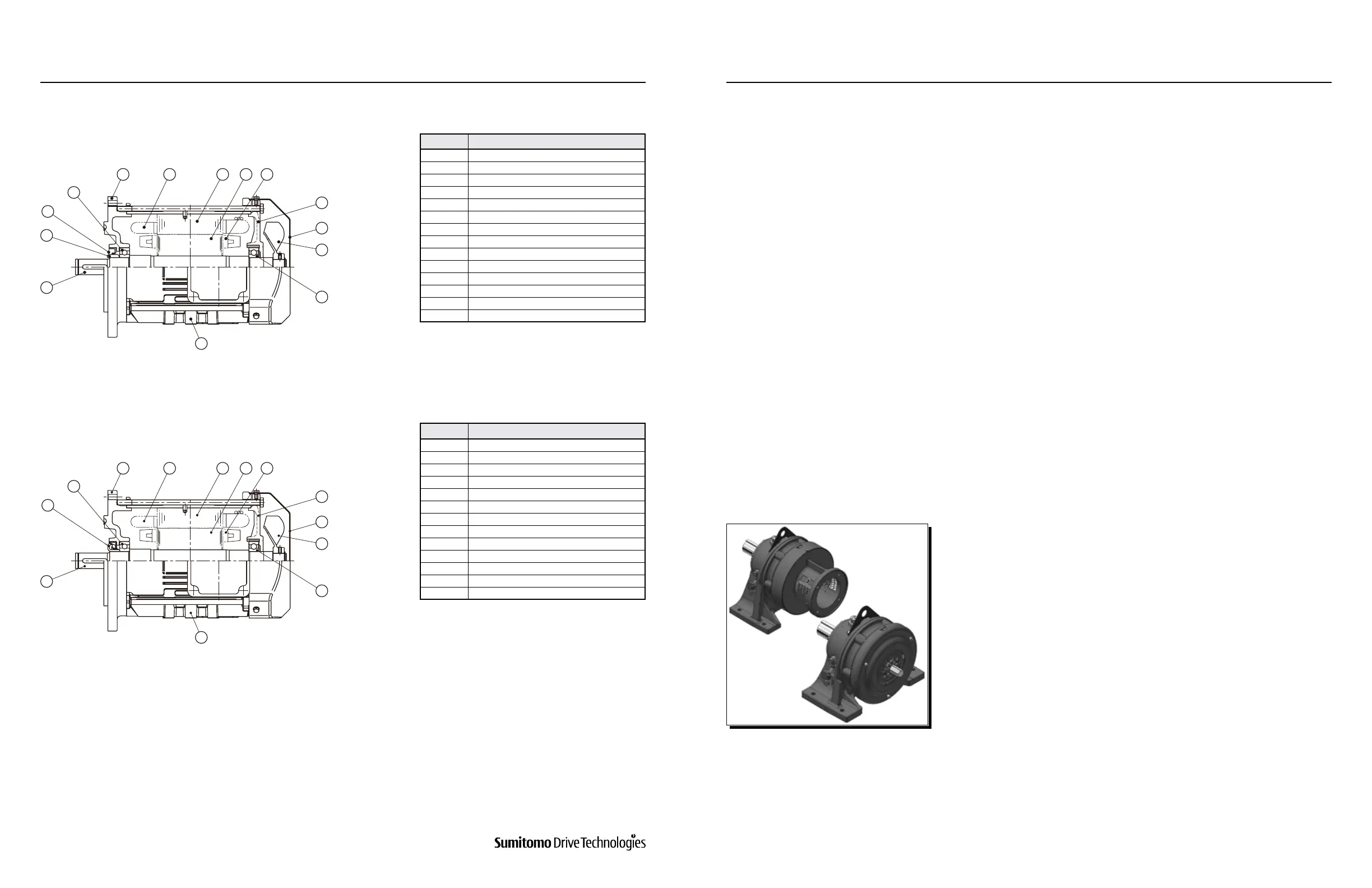
Figure 10-17: Direct-Coupled Motor for Cyclo® Drive
(Sealed Bearing, Oil Seal Structure) (Example: N-100L 2.2kW 4P)
Figure 10-18: Direct-Coupled Motor for Cyclo® Drive
(Sealed Bearing, Slinger Collar Structure) (Example: N-100L 2.2kW 4P)
Table10-8: Principal Parts of Motor
Table10-9: Principal Parts of Motor
2
10
11
1
2
3
4
56789
3
Code Part Name
1 Anti-Load Side Motor Shaft Bearing
2 Fan
3 Fan Cover
4 Anti-Load Side Cover
5 Rotor Conductor
6 Rotor Core
7 Stator Core
8 Stator Windings
9 Motor Flange Bracket
10 Load Side Motor Shaft Bearing
11 Oil Seal
12 Oil Seal Collar
13 Motor Shaft
14 Frame
Code Part Name
1 Anti-Load Side Motor Shaft Bearing
2 Fan
3 Fan Cover
4 Anti-Load Side Cover
5 Rotor Conductor
6 Rotor Core
7 Stator Core
8 Stator Windings
9 Motor Flange Bracket
10 Load Side Motor Shaft Bearing
11 Slinger Collar
12 Motor Shaft
13 Frame
10
11
1
2
3
4
2
Cyclo® Reducers/Gearmotors are designed to provide maximum ease when disassembling and reassembling; they
require no special maintenance skills. During the process, please refer to Table 10-1 and Figures 10-1 to 10-12 for
component identication.
The following procedures and precautions are recommended at time of disassembly and assembly:
•
Perform work in a safe area free of dust and humidity, and use your proper personal protective equipment (PPE).
•
Use a soft or plastic hammer when required. Take care not to damage parts, i.e., coil, bearings, seals, etc.
•
Inspect all components and replace as necessary.
•
Be extremely careful when handling Cyclo® discs and spacer ring for discs.
Remove the complete Cyclo® Reducer/gearmotor from the driven machine.
For oil lubricated units, remove the plug at the bottom of the oil gauge to drain all oil from the unit. Refer to Section
8.3.5 Draining Procedure.
1
2
For reducers with free input shaft equipped with a cooling fan, remove
the cooling fan cover and fan.
3
www.SumitomoDrive.com
Cyclo® 6000 Operating and Maintenance Manual
Cyclo® 6000 Cyclo® 6000
Cyclo® 6000 Operating and Maintenance Manual
82 83
10. CONSTRUCTION DRAWINGS 11. CYCLO® ASSEMBLY / DISASSEMBLY
11. Cyclo® Assembly / Disassembly
11.1 Disassembly
10.3 Motor