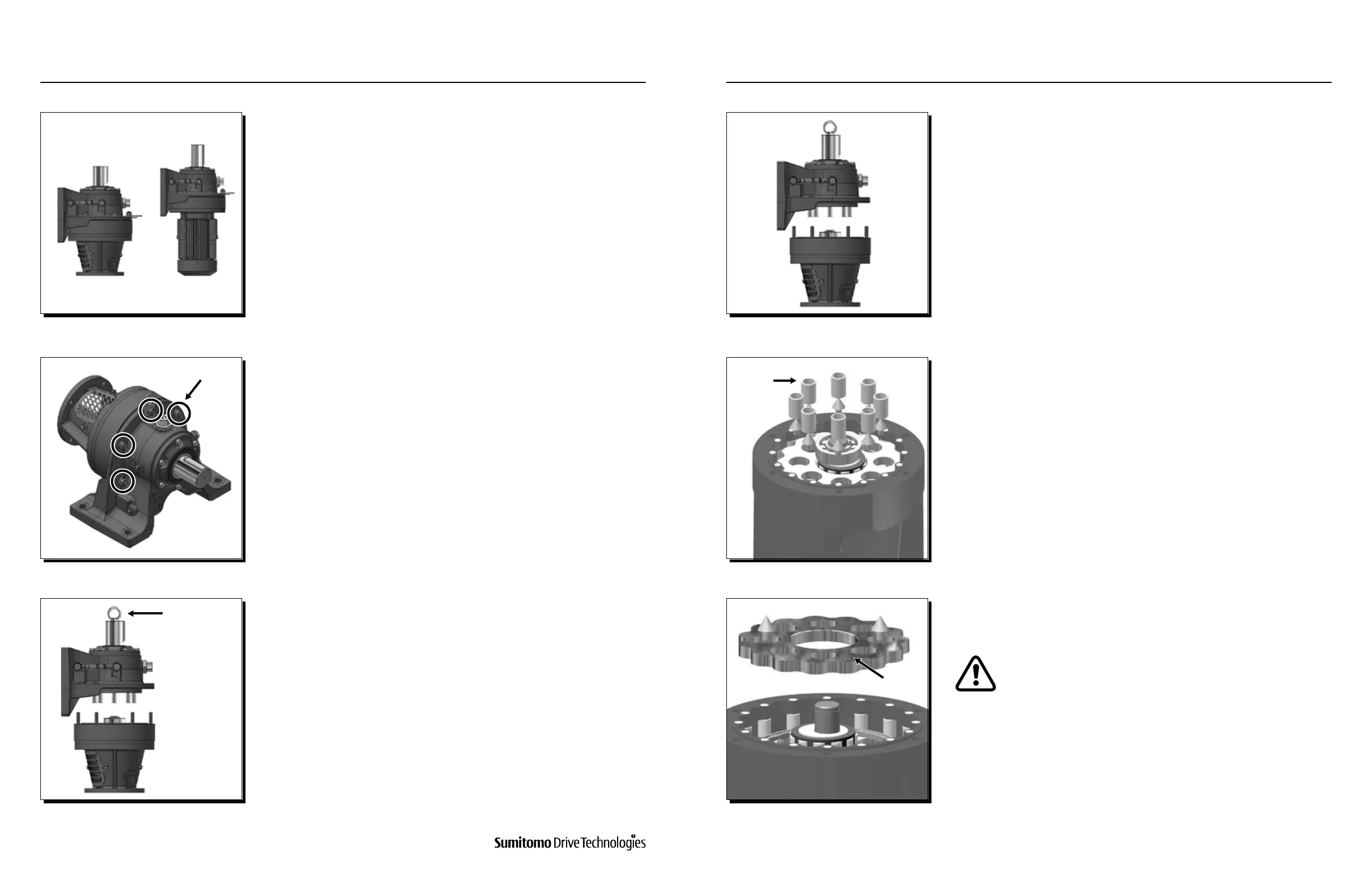
Stand the unit on a solid base with its high speed shaft side down.
If the reducer has C-Face adaptor and coupling, remove the motor and
coupling before following the procedure outlined above.
As a nal step, remove the adaptor and cooling fan.
For gearmotor units, place Cyclo® gearmotor vertically with slow speed
shaft upward.
Lift the slow speed side, thus separating the unit into two parts so that
the inner mechanism can be removed.
If the unit will not separate easily, gently drive a wedge between ring
gear housing and slow speed shaft casing.
NOTE: If this produces a burr, be sure to remove it before reassembly.
Remove the through bolts for the high speed end shield and ring gear
housing.
Take out the slow speed shaft rollers.
Check the slow speed shaft pins (22) to see whether any rollers have
adhered to them.
To lift the slow speed side, attach an eyebolt to the tapped hole at the
end of the slow speed shaft and use a hoist or chain block.
Using both hands, lift out the top cycloid disc (33) on the slow speed side.
The cycloid disc is made from heat-treated bearing steel
and the spacer ring is cast iron. Take care not to strike them
together while handling.
4 7
5 8
6 9
Eye Bolt
Cycloid Disc
Slow Speed
Rollers
Ring Gear Housing Bolts
www.SumitomoDrive.com
Cyclo® 6000 Operating and Maintenance Manual
Cyclo® 6000 Cyclo® 6000
Cyclo® 6000 Operating and Maintenance Manual
84 85
11. CYCLO® ASSEMBLY / DISASSEMBLY11. CYCLO® ASSEMBLY / DISASSEMBLY