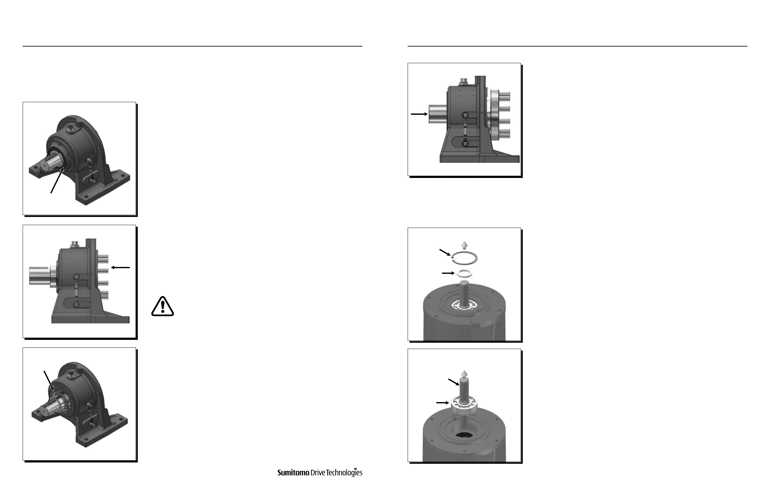
Remove oil seal (3) and oil seal housing.
1
With a wooden or hard rubber mallet, tap the inner end of the slow
speed shaft to expose the retaining ring from the outer raceway of the
bearing.
Note: Retaining ring is part of bearing A (5).
2
11.2 Output Casing Subassembly
11.3 High Speed End Shield Subassembly
In the event that the slow speed shaft should be removed from the output casing assembly, please follow these steps to
remove the slow speed shaft (1) with its bearings from the output casing (8 or 39, depending on Cyclo conguration).
Cyclo® reducers, in the event that the high speed end shield subassembly needs to be disassembled:
Rap the outer end of the slow speed shaft with a wooden or hard rubber
mallet, and remove it from the casing.
4
Remove the retaining ring (5).
3
The high speed shaft (26) with bearings is removed from the high speed
shaft end shield (20) by tapping the shaft end after rst taking o the
retaining ring (11).
1
Spacer
Snap Ring
Bearing
High Speed Shaft
Make sure to avoid hitting the SSS pins (22) and Bearing C’s
(12) raceway. Failure to do so may compromise re-assembly of
the unit.
Oil Seal
Retaining Ring
www.SumitomoDrive.com
Cyclo® 6000 Operating and Maintenance Manual
Cyclo® 6000 Cyclo® 6000
Cyclo® 6000 Operating and Maintenance Manual
88 89
11. CYCLO® ASSEMBLY / DISASSEMBLY11. CYCLO® ASSEMBLY / DISASSEMBLY