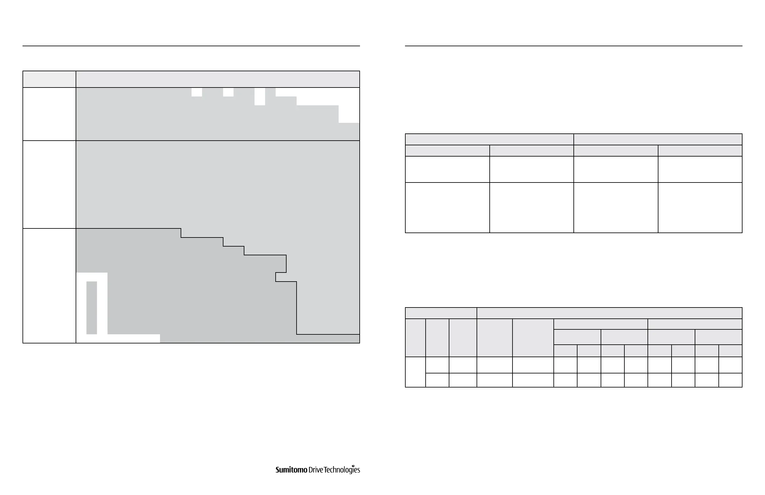
Table 8-5: Lubrication for Vertical Mount Double Reduction
Frame Size
Reduction Ratio
104 121 143 165 195 231 273 319 377 473 559 649 731 841 1003 1015 1247 1479 1849 2065 2537 3045 3481 4437 5133 6177
7569
6060DA, 6065DA
6070DA, 6075DA 2537
6090DA, 6095DA 5133
6100DA, 6105DA Maintenance Free Grease
6120DA, 6125DA
6120DB, 6125DB
6130DA, 6135DA
6130DB, 6135DB
6130DC, 6135DC
6140DA, 6140DB, 6140DC
6145DA, 6145DB, 6145DC
6160DA, 6165DA Grease
6160DB, 6165DB
6170DA, 6175DA
6170DB, 6175DB
6180DA. 6185DA
6160DC, 6165DC
473
6170DC, 6175DC
841
6180DB. 6185DB
1015
6190DA, 6195DA
2065
6190DB, 6195DB
6205DA, 6205DB 165 1849
6215DA, 6215DB 121 Oil
2537
6225DA, 6225DB
6235DA, 6235DB
6245DA, 6245DB
6255DA, 6255DB
6265DA
6275DA
377
www.SumitomoDrive.com
Cyclo® 6000 Operating and Maintenance Manual
Cyclo® 6000 Cyclo® 6000
Cyclo® 6000 Operating and Maintenance Manual
40 41
Table 8-6: Plunger Pump Type
Table 8-7: Positive Displacement (Trochoid) Pump Type
Forced Lubrication For Vertical Units
Small Size Pump Large Size Pump
Frame Size Ratio Frame Size Ratio
6160,6165,6170,6175,
6180,6185,6190,6195
See Table 8-4
6205, 6215, 6225, 6235,
6245, 6255, 6265, 6275
See Table 8-4
6160DC, 6165DC, 6170DC,
6175DC, 6180DB, 6185DB,
6190DA, 6195DA, 6190DB,
6195DB
See Table 8-5
6205DA, 6205DB, 6215DA,
6215DB, 6225DA, 6225DB,
6235DA, 6235DB, 6245DA,
6245DB, 6255DA, 6255DB,
6265DA
See Table 8-5
Cyclo Drive Trachoid Pump
[1,2]
Type
Frame
Size
Reduction
Ratio
Pump Type Pump Motor
50 HZ 60 HZ
Flow
Max
Pressure
Flow
Max
Pressure
gal/min I/min psi kgf/cm
2
gal/min I/min psi kgf/cm
2
Vertical
Shaft
6275
29, 43,
59, 87
TOP216HA-VB3 1 HP (0.75 kW) 4P 6.3 24.0 113.8 8 7.6 28.8 71.1 5.0
6275DA All TOP204HA-VB3 1/2 HP (0.4 kW) 4P 1.6 6.0 227.6 16 1.9 7.2 163.6 11.5
Plunger Pump Lubrication
Positive Displacement (Trochoid) Pump Lubrication
The plunger pump (Figure 10-2, Part 40) is automatically operated by a cam (Figure 10-2, Part 47) tted on the slow
speed shaft (Figure 10-1, Part 1). The number of pumping cam teeth required is in direct relation to the reduction
ratio and frame size. Please consult the factory for input speeds other than standard.
Forced oil lubrication is accomplished by using a positive displacement pump and motor that requires an additional
electric power source. It is recommended that the main motor be interlocked with the pump motor to avoid operation
without lubrication. The pump must be started 30 seconds or longer before the main motor is operated.
Notes: [1] Consult the factory when using an inverter.
[2] A relief valve, pressure set at 42.7 psi (3 kgf/cm
2
), is a standard attachment on the trochoid pump.
8. DAILY INSPECTION AND MAINTENANCE 8. DAILY INSPECTION AND MAINTENANCE