If the brake lining is so heavily worn that gap adjustment is required, follow these steps:
a. Remove shifting pins (5) and brake release lever (6).
b. Remove the cover (13). Remove fan (15) by removing retaining ring (14). Remove V-Ring (24) waterproof seal (26)
and waterproof cover (25).
c. Insert a gap gage into the space between the stationary core (1) and armature plate (4) and rotate the nut (16) at
the tip of the stud bolt (19) clockwise until the gap measures an appropriate size. If the gap is too large to adjust
by this procedure, decrease the number of adjusting washers (18) in use. Evenly adjust the three nuts (16) until
the gaps at the three circumferential points are equal and fall within the specication range shown in Table 8-26.
d. After completing the gap adjustment, turn the system power on and o a few times to check the brake
performance.
e. Replace waterproof cover (25), waterproof seal (26), V-Ring (24), fan (15), retaining ring (14), cover (13), shifting
pins (5), and brake release lever (6).
5. Gap Adjustment
Follow these steps to replace the brake lining when its thickness has reached the allowable limit shown in Table 8-27,
or when sleeve adjustment is no longer an eective means of gap adjustment:
a. Remove shifting pins (5) and brake release lever (6).
b. Remove the cover (13). Remove fan (15) by retaining ring (14). Remove V-Ring (24) waterproof seal (26) and
waterproof cover (25).
c. Remove all three nuts (16)
d. Remove the brake shoe (8) and take out the brake lining (9).
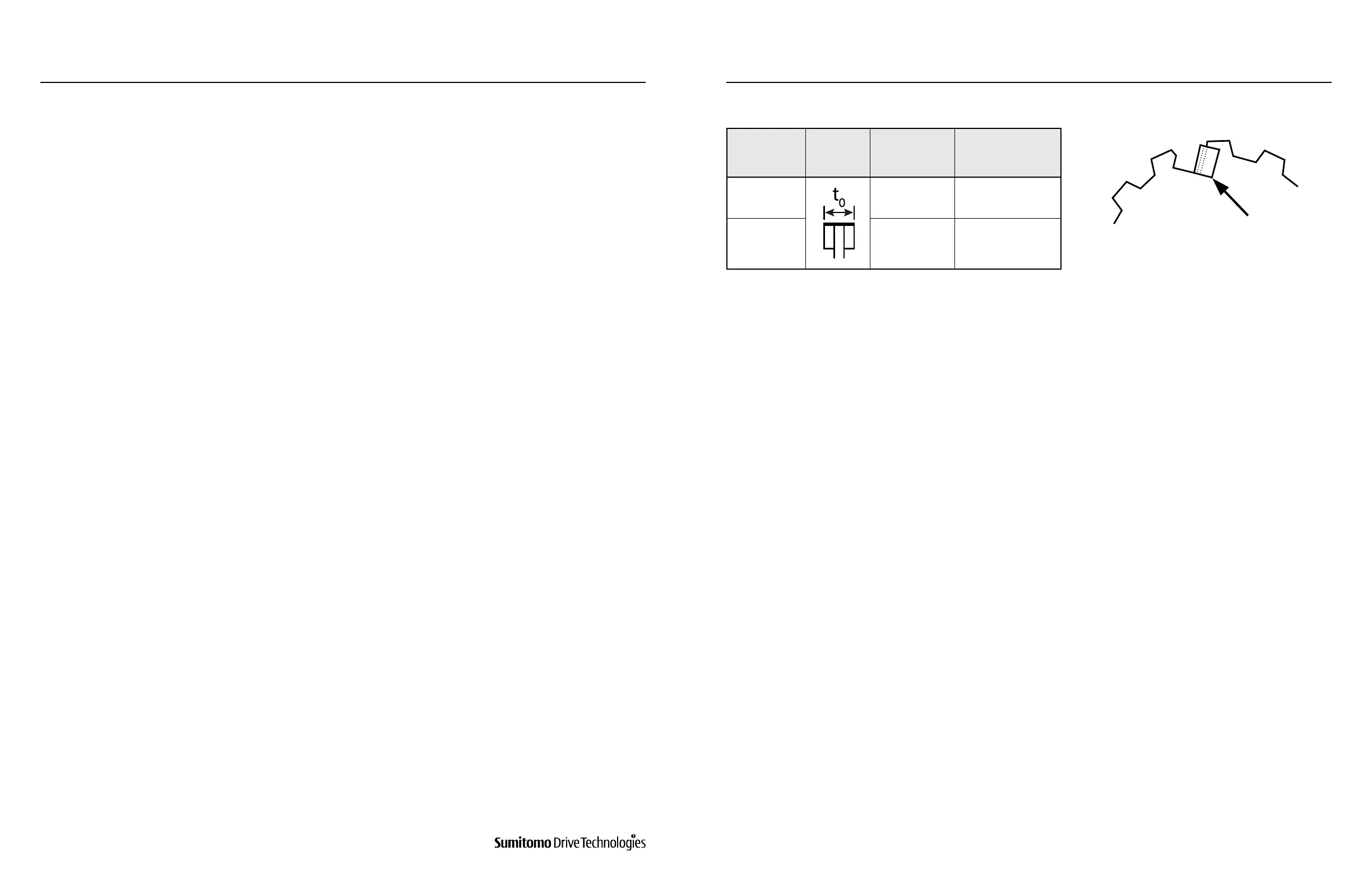
e. Fix the leaf spring (10) as shown in Figure 8-13.
f. Apply a small amount of grease along the spline of the new brake lining (9), taking care not to apply any to the
wear surface.
g. Fit the new brake lining (9) onto the hub (11) and check that it moves smoothly. Remove any excess grease.
h. After reassembling the brake, measure gap G. If the gap is out of the specication range, adjust by rotating the
gap adjusting nut (16).
i. Turn the system power on and o a few times to check the brake performance. If no abnormalities are detected,
replace the fan (15), retaining ring (14) and cover (13).
j. Measure gap G. Readjust if the gap is not within the specication value range.
k. Turn the system power on and o a few times to check the brake performance. If no abnormalities are detected,
replace waterproof cover (25), waterproof seal (26), V-Ring (24), fan (15), retaining ring (14), cover (13), shifting
pins (5) and brake release lever (6).
6. Brake Lining Replacement
Brake Type
Brake Lining
Dimension
Initial Thickness
t
0
,in (mm)
Allowable Thickness
t
0
,in (mm)
FB-5E, FB-8E 0.276 (7.0) 0.236 (6.0)
FB-10E, FB-15E 0.398 (10.4) 0.331 (8.4)
Table 8-27: Brake Lining Size Figure 8-13: Leaf Spring
www.SumitomoDrive.com
Cyclo® 6000 Operating and Maintenance Manual
Cyclo® 6000 Cyclo® 6000
Cyclo® 6000 Operating and Maintenance Manual
66 67
8. DAILY INSPECTION AND MAINTENANCE 8. DAILY INSPECTION AND MAINTENANCE