10 Manual BBB4_ENG_01_2016_991301
Installation onto Driven Shaft
Taper-GripBushing
Taper-GripBushingIntroduction
The keyless Taper-Grip bushing system provides a simple and reliable shaft attachment
for Sumitomo speed reducers and gearmotors. This system allows bi-directional shaft
rotationoperationwithapowerful,slip-freegrip.Toassurepeakperformanceofyour
equipment,pleaseread,understandandfollowtheseinstallationinstructions.
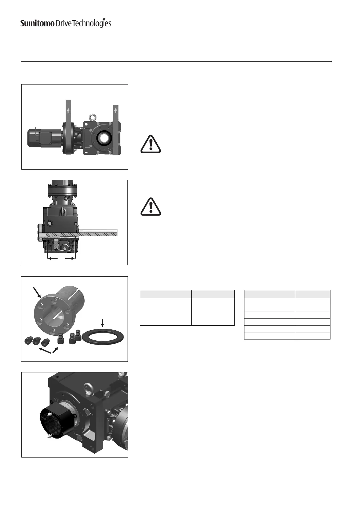
PriortoinstallationoftheBBB4ontothedrivenshaft,ensurethatthe
shaft length meets or exceeds the minimum shaft engagement value
“TT” detailed in Table 1.
Do not operate unit until the torque arm has been attached to the unit
and fixed to a rigid structure. The torque arm prevents counter-rotation
during unit operation. Refer to torque arm installation section in this
manual for instructions.
CAUTION: The BBB4 must be externally supported prior to insertion of
driven shaft into bushing. External support MUST be maintained until all
bushing socket head cap screws have been tightened to the appropriate
operational torque.
ComponentsofTaper-GripBushing
Asshowninthegureontheleft,theTaper-Gripbushingincludesthebushing,
thrust collar,andsocket head cap screws.
Table 1. Driven Shaft Tolerance
[1]
andMinimumShaftEngagement(TT)
Taper-GripBushingInstallationontoDriven
Shaft
1
Remove bushingcover if unit was supplied with one.
Taper-GripBushing
Socket Head Cap Screws
Thrust Collar
TT
BBB4 Size TT mm
4A 208
4B 242
4C 279
4D 326
4E 359
4F 412
Shaft Diameter mm Tolerance μm
30 - 50 +0 / -39
50 - 80 +0 / -46
80 - 120 +0 / -54
120 - 180 +0 / -63
Note: [1] Based on ISO/JIS/DIN h8

 Loading...


