14 Manual BBB4_ENG_01_2016_991301
Installation onto Driven Shaft, continued
Keyed Hollow Bore
Keyed Hollow Bore Installation
Do not operate unit until the torque arm has been attached to the unit and fixed to a rigid structure. The torque arm prevents
counter-rotation during unit operation. Refer to torque arm Installation section in this manual for instructions.
CAUTION: The BBB4 must be externally supported prior to insertion of driven shaft into hollow bore.
Bore and Shaft Tolerance Specifications
•Unlessotherwisespecied,thetoleranceoftheHollowShaftBoretoleranceH8.
•Ifapplicationinvolveshighshockloadingand/orlargeradialloads,ashafttoleranceofjs6ork6isrecommended.
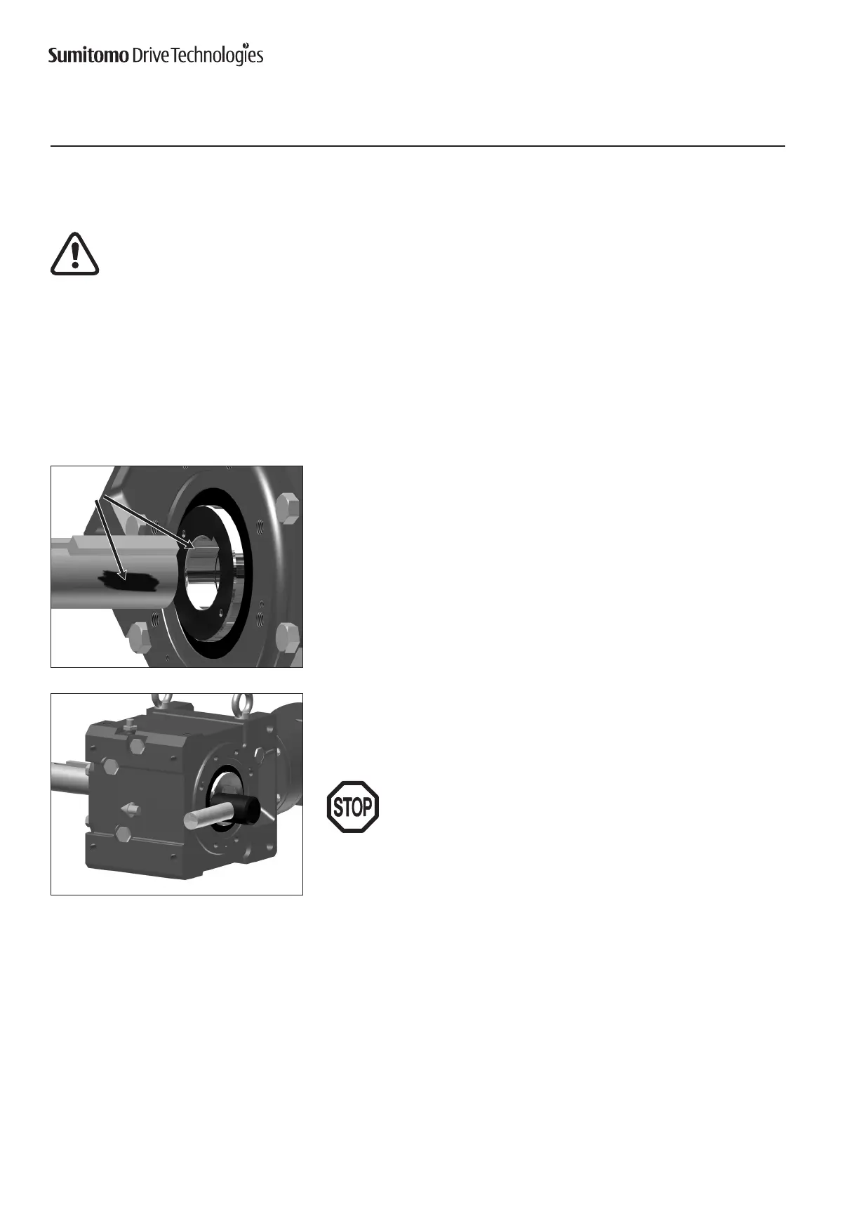
Anti-sieze
compound
Keyed Hollow Bore Installation
onto Driven Shaft
1
Apply anti seize compound to the driven shaft surface and inside the reducer keyed
hollow bore.
2
Align the driven shaft with the reducer/gearmotor bore and carefully slide unit onto
the driven shaft to the desired location.
Ifthetistight,strikeonthekeyedhollowborewithawoodenorhard
rubber mallet to assist in the assembly.
Ifusingamalletduringinstallation,strikeonly against the unit’s steel
keyed hollow bore. Do not strike the reducer housing or oil seal as
damagetothebearings,housingand/orsealsmayoccur.
Note:Ifthetistight,useajigsuchastheoneshowninTable3toease
assembly. Sumitomodoesnotsupplyamountingjig.Thisinforma-
tion is provided for reference only.

 Loading...


