16 Manual BBB4_ENG_01_2016_991301
Size
Model
(Typical)
Bolt
Bolt Torque
N•m
4A TAS-3071-55x68
10 x M6x25
ISO/JIS grade 10.9
12
4B TAS-3081-65x80
7 x M8x30
ISO/JIS grade 12.9
34
4C TAS-3081-75x100
12 x M8x35
ISO/JIS grade 12.9
34
4D TAS-3093-85x110
12 x M10x45
ISO/JIS grade 12.9
68
4E TAS-3081-100x140
10 x M12x45
ISO/JIS grade 12.9
118
4F TAS-3071-120x165
8 x M16x55
ISO/JIS grade 12.9
290
Table4.ShrinkDiscBoltTighteningTorques
2
Align the driven shaft with the bore of reducer/gearmotor bore and carefully slide
unit onto the driven shaft to the desired location.
•Ifthetistight,strikeonthereducerhollowborewithamallettoassistintheassembly.
Ifusingamalletduringinstallation,strikeonly against the unit’s steel
hollow bore. Do notstrikethereducerhousingoroilseal,asdamageto
thebearings,housing,and/orsealsmayoccur.
Ifthetistight,useajigsuchastheoneshownintheKeyedHollowBore
Installation section to ease assembly. Sumitomo does not supply a
mountingjig.Thisinformationisprovidedforreferenceonly.
Installation onto Driven Shaft, continued
Shrink Disc Type Hollow Bore
1
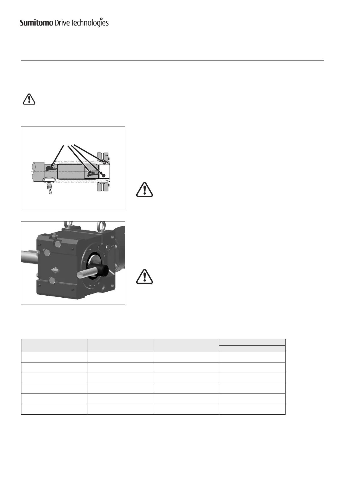
Cleananddegreasecontactsurfaces;reducershaftandbore,andthemachine
driven shaft.
Apply Molykote 321 or an equivalent dry film lubricant to the driven shaft shoulder
opposite from the shrink disc.
Do Not apply any friction minimizing compound to the driven shaft at or
near the shrink disc.
Degrease
these areas
Apply Molykote 321
to this shaft area only
Shrink Disc Type Hollow Bore Installation onto Shaft
Beforeplacingunitontodrivenshaft,donotapplygrease,oil,oranti-seizepastetotheentiredrivenshaftortothebore
of the shrink disc. Use of these friction-minimizing products will adversely affect the ability of the unit to transmit torque.
Never tighten locking screws before shaft installation. Inner ring may become permanently contracted even at low tightening
torques.