3
Oncedrivenshafthasbeencompletelyinsertedintotheunit’skeyedhollowbore,
securetheshaftinplaceusingakeeperplateasshowntotheleft,orsomeother
means of securing the unit to the driven shaft.
Do not operate unit until the torque arm has been attached. Refer to
the Torque Arm Installation section in this manual for instructions.
Manual BBB4_ENG_01_2016_991301 15
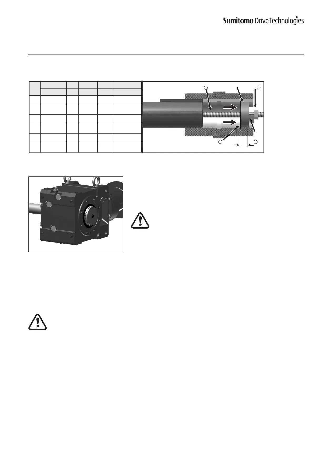
Installation onto Driven Shaft, continued
Keyed Hollow Bore, Shrink Disc Type Hollow Bore
Size
a b c d e
CC(ISO/JIS) A2 Bearing Nut Threaded Rod
4A 40 25 51104 M16 M16 x 250
4B 60 25 51105 M20 M20 x 300
4C 70 25 51105 M20 M20 x 300
4D 90 35 51107 M24 M24 x 400
4E 100 35 51107 M24 M24 x 400
4F 120 46 51109 M30 M30 x 450
Table3.JigDimensions(mm)
RetainingRinga
Ball
Bearing
c
Threaded Rod e
Nut d
A2
ShrinkDiscTypeMountingIntroduction
The keyless Shrink Disc provides a reliable commodity shaft attachment for Sumitomo speed reducers and gearmotors. This system
allowsbi-directionalshaftrotationoperationwithapowerful,slip-freegrip.
Toassurepeakperformanceofyourequipment,pleaseread,understandandfollowtheseinstallationinstructions.
Do not operate unit until the torque arm has been attached to the unit and fixed to a rigid structure. The torque arm prevents
counter-rotation during unit operation. Refer to torque arm Installation section in this manual for instructions.
CAUTION:TheBBB4mustbeexternallysupportedpriortoinsertionofdrivenshaftintohollowbore.ExternalsupportMUST
be maintained until all shrink disc socket head cap screws have been tightened to the appropriate operational torque.
Bore and Shaft Tolerance Specifications
• RefertothecertiedoutlinedrawingorBBB4Catalogforrecommendedmachineshaftdimensions.
• Unlessotherwisespecied,thetoleranceoftheShrinkDiscBoreH8.
• Ifapplicationinvolveshighshockloadingand/orlargeradialloads,ashafttoleranceofjs6ork6isrecommended.