Manual BBB4_ENG_01_2016_99130119
Torque Arm Installation, continued
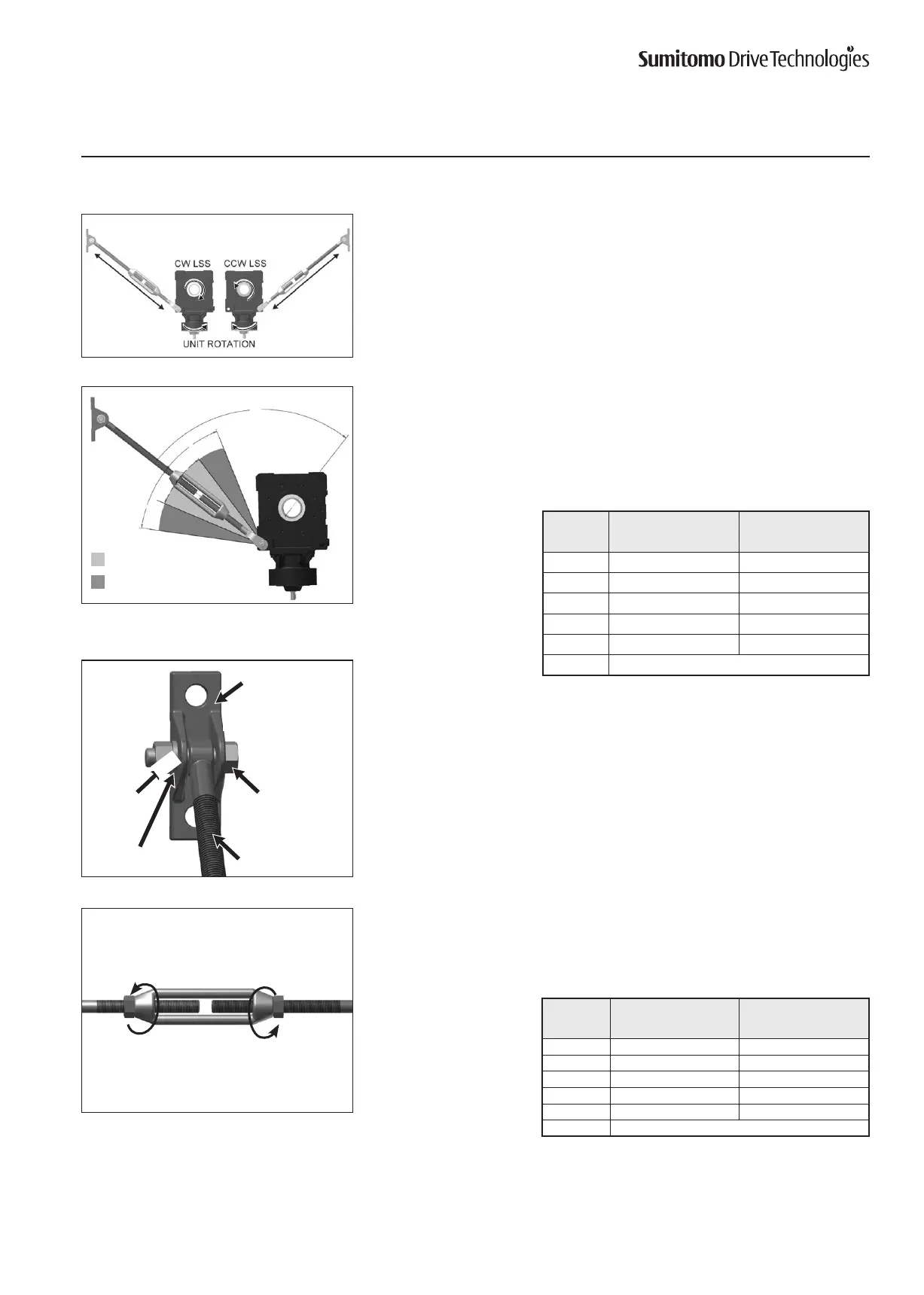
Turnbuckle Type Torque Arm
3
Position the torque arm so it will be in tension during unit operation and mount the
fulcrum mounting bracket to suitable structure or foundation. Consider installing
two torque arms for reversing applications to allow torque arm to be in tension for
each direction of rotation.
Mounting hardware for fulcrum mounting bracket are NOT supplied by Sumitomo.
4
Position the torque arm as close as possible to 90° relative to the unit output bore /
driven equipment shaft.
Sumitomo does not recommend combining torque arm assemblies to achieve a
greater overall length.
5
Assemble the threaded
armtothefulcrummountingbracket,asshown.
Someadjustmentoftheturnbucklemayberequiredtolengthenorshortenthe
overall length.
Secureitwiththeappropriatenut,boltandlockwasher.
•Inserttheboltthroughthebracketsandthreadedarmeyelet.
•Placethelockwasherontheboltandsecurewithnut.
6
Ifturnbucklehexnutsweresupplied,securetheturnbucklepositionbyadjusting
the previously installed turnbuckle nuts.
OPTIMUM MOUNTING
ACCEPTABLE MOUNTING
Threaded Arm
Bolt
Nut
Lock Washer
MountingBracket
Unit
Size
Bolt Size
[1]
N•m
A M16 x 65 206 – 227
B M16 x 80 206 – 227
C M16 x 80 206 – 227
D M16 x 80 206 – 227
E M16 x 80 206 – 227
F Consult Factory
Table7.BoltTighteningTorques
Note: [1] Bolt Class equal to ISO/JIS Class 8.8
90
30
30
15
15
Unit
Size
Nut Size
[1]
N•m
A M20 392 – 431
B M24 686 – 755
C M24 686 – 755
D M24 686 – 755
E M24 686 – 755
F Consult Factory
Table8.NutTighteningTorques
.