Manual BBB4_ENG_01_2016_991301 23
5
Place a soft-metal (i.e. brass) bar against the flange of the Taper-Grip bushing and
carefully strike end of bar with a hammer to release the bushing.
6
Apply a liquid penetrant to the shaft where it contacts the bushing. Allow time for
the liquid to settle between the shaft and the bushing wall. Once the penetrant has
settledadequately,carefullyremovetheBBB4fromthedrivenshaft.
If the Taper-Grip bushing releases but the unit cannot be removed from the driven
shaft,apullermayneedtobeappliedtothebushingangetopulltheunitfree
from the shaft.
Removal of BBB4 with Keyed Hollow Bore
Beforestartingunitremovalprocess,ensurethatelectricalpowertounithas
been safely locked out and that electrical connections to the unit have been
disconnected.
1
Remove safety cover and the shaft-retaining device from the driven shaft.
Removal from Driven Shaft, continued
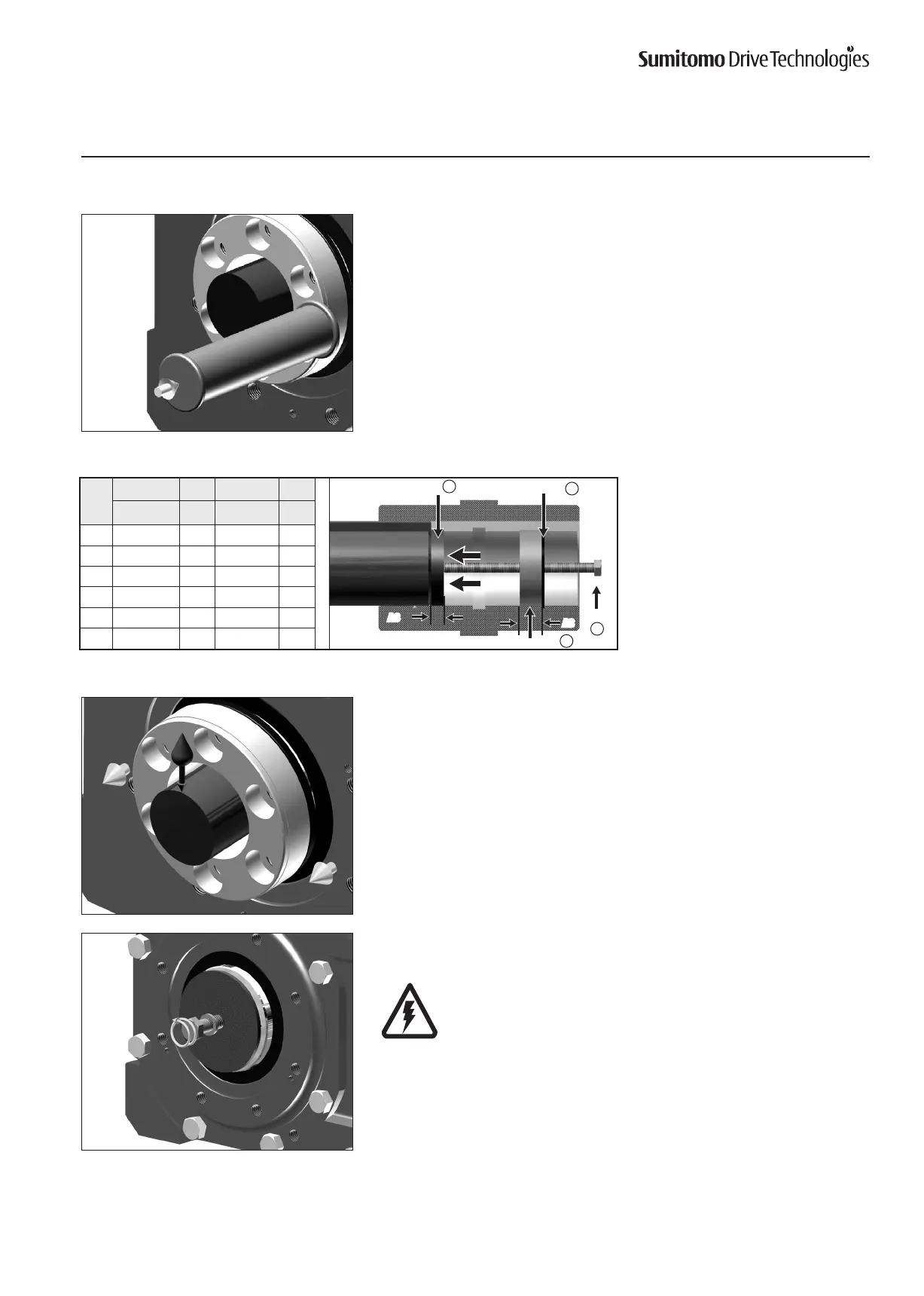
Removal of BBB4 with Keyed Hollow Bore
Size
a f g h
CC(ISO/JIS) A3 BOLT A8
4A
55 19 M24x250 6
4B
65 19 M24x300 6
4C
75 19 M24x300 5
4D
85 24 M30x400 5
4E
100 19 M30x400 5
4F
120 30 M36×450 7
Table12.RemovalJigDimensions
Ifshaftremovalisdicult,ajigsuchastheoneshowninTable12maybeusedtoeasethe
removal process. Sumitomodoesnotsupplytheremovaljig.
This information is supplied for reference only.
InternalSnapRinga
Spacer: Threaded f
Bolt
g
Thrust Disc h
A3
A8