38 Manual BBB4_ENG_01_2016_991301
Motor installation, continued
Electrical installation
Table 28. Conduit threat sizes
Frame Conduit threat Frame Conduit threat
63-71
1xM16x1,51xM25x1,5 180 2xM40x1,5
80-132S 2xM25x1,5 200-225 2xM50x1,5
132M-160 2xM32x1,5 250 2xM63x1,5
Cable glands must comply at least with the motor protection class specified on the model plate.
Unused cable glands must be closed depending on the type of motor protection. Existing plugs must be tightened firmly.
Please refer to the rating plate and these operating instructions as well as the current catalogue for technical data and infor-
mation on the permissible operating conditions. You will find information on special versions on your order confirmation. If
anythingisunclear,weurgentlyrecommendyoutocontactthefactoryoryoursalescentregivingthemodeldescriptionand
the serial number.
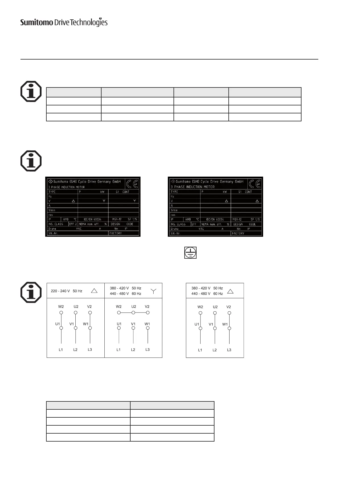
Motor 0.12 - 4.0 kW Motor 5.5 - 55 kW
Connect the protective earthing conductor to this terminal.
A circuit diagram is located in the terminal box. The motors can be connected to the terminal board depending on the con-
nectionvoltageasfollows:
The rated voltage range as set out in EN 60 034-1 applies to the specified voltages with a ± 5 % voltage or ± 2 % frequency
deviation.
Thefollowingtighteningtorquesapplytothethreadedboltsontheterminalboard:
Table29.Tighteningtorques
Screw thread: PermissibletighteningtorqueinNm
M4 1.2
M5 2.5
M6 4.0
M8 7.5
 Loading...


