10 Operation & Maintenance Manual
Cyclo® HBB
Cyclo® HBB
Installation onto Driven Shaft
Using Taper-Grip® Bushing
8
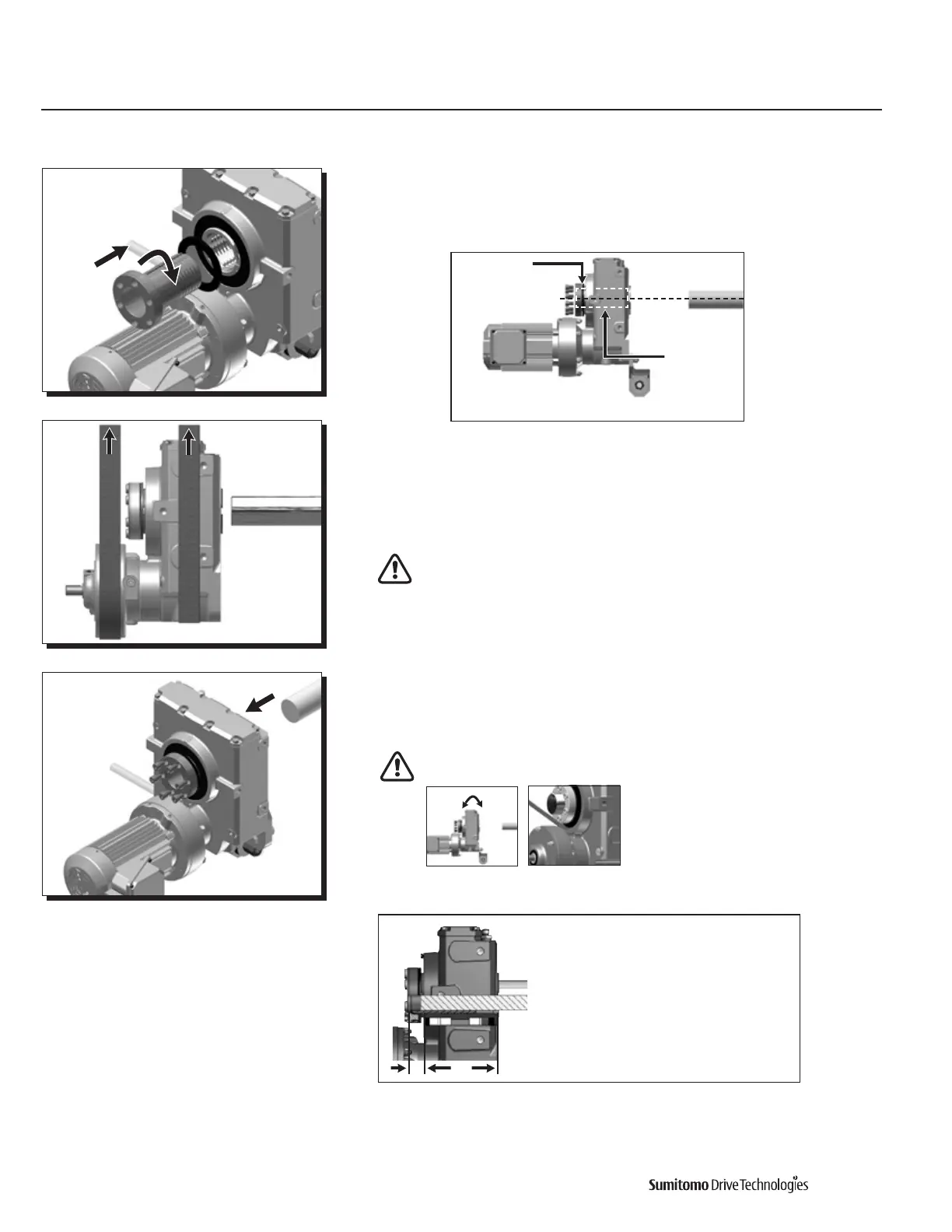
Unscrew Taper-Grip® bushing Cyclo ® HBB leaving approximately 1 mm gap
between the bushing flange and thrust collar.
9
Externally support the Cyclo® HBB before inserting the driven shaft into the bushing.
Maintain external supportuntilallbushingsocketheadcapscrewsaretightened
to the appropriate operational torque (Step 12).
Do not apply grease, oil, or anti-seize paste to the driven shaft or
the bushing bore before placing the unit onto driven shaft. Use of these
friction-minimizing products will adversely affect the ability of the unit to
transmit torque.
10
Mount the Cyclo® HBB onto the driven shaft.
Do not rock or pry the unit.
Table 1. Minimum Shaft Engagement
Leave 1 mm gap
between bushing
flange and thrust
collar.
Flush
The shaft should
be flush to the
bushing flange.
Be sure that bushing and shaft
are aligned, and Cyclo HBB
weight is supported.
Align
Cyclo Min. Shaft Max. Depth
HBB Size Engagement to Shaft End
TT(in.) TS(in.)
Z 4.47 1.22
A 5.00 1.38
B 5.67 1.77
C 7.36 1.57
D 8.07 1.97
E 8.86 2.01
TS TT

 Loading...


