8 Operation & Maintenance Manual
Cyclo® HBB
Cyclo® HBB
Installation onto Driven Shaft
Taper-Grip® Bushing Installation
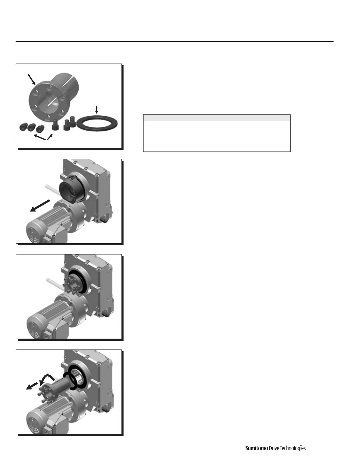
Taper-Grip® Bushing
SocketHeadCapScrews
Thrust Collar
Introduction
ThekeylessTaper-Grip®Bushingsystemprovidessimpleandreliableshaftattachmentfor
Sumitomo speed reducers and gearmotors. This system allows bi-directional shaft rotation
andstop-startoperationwithapowerful,slip-freegrip.Toassurepeakperformanceof
your equipment, please read, understand and follow these installation instructions.
Taper-Grip® Bushing Driven Shaft Tolerances
Parts
As shown in the figure on the left, the Taper-Grip® Bushing includes the bushing,
thrust collar, and socket head cap screws.
Taper-Grip® Installation onto Driven Shaft
1
Remove the Taper-Grip® bushing safety cover if the unit includes one.
2
Loosen socket head cap screws.
3
Remove (unscrew) Taper-Grip® bushing from the unit. Slide the thrust collar onto the
Taper-Grip® bushing.
Shaft Diameter (inches) Shaft Tolerance (inches)
3
/
4
” — 1
1
/
8
” +0”/ – 0.0013”
1
3
/
16
” — 2” +0”/ – 0.0015”
2
1
/
16
” — 3
1
/
8
” +0”/ – 0.0018”
3
3
/
16
” — 4
3
/
4
” +0”/ – 0.0021”
4
13
/
16
” — 6
1
/
2
” +0”/ – 0.0025”
The required tolerance is h8.

 Loading...


