Cyclo® HBB
Operation & Maintenance Manual 13
Cyclo® HBB
Installation onto Driven Shaft
Keyed Hollow Bore Installation
Keyed Hollow Bore Installation
onto Driven Shaft
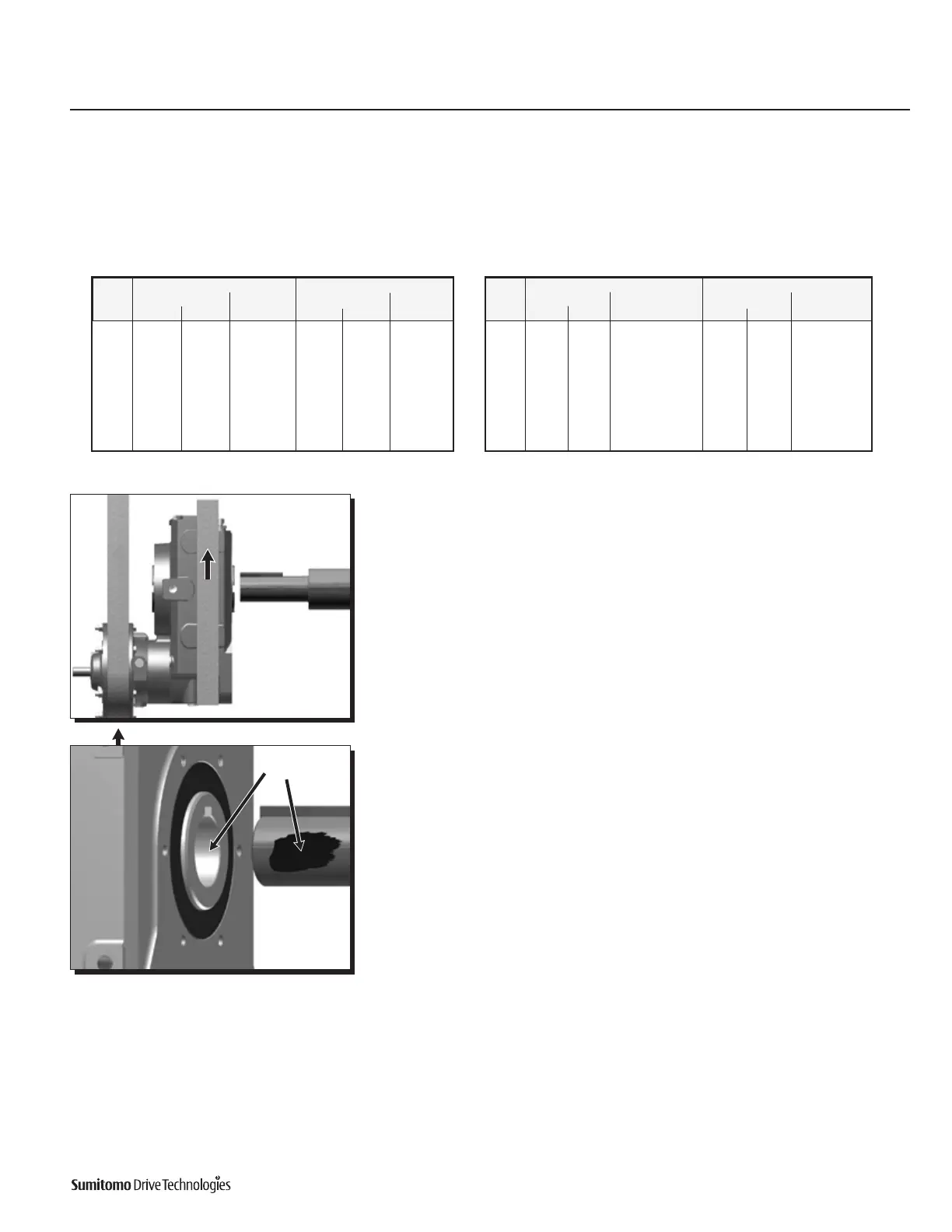
1
ExternallysupporttheCyclo®HBBbeforeinsertingthedrivenshaftintothekeyed
hollow bore. Maintain external support until the shaft is completely inserted and
secured to the unit.
2
Applymolybdenumdisuldegreasetothedrivenshaftsurfaceandinsidethekeyed
hollow bore.
Grease
Table 4. Driven Shaft Tolerances –
With Shock Load or Large Radial Load
Inch Metric, mm
Frame Shaft Dia
Tolerance
Shaft Dia.
Tolerance
Size Min. Max. Min. Max.
Z 1-3/16 1-1/2 +0.0007 / +0.0001 30 40 +0.018 / +0.002
A 1-3/4 1-15/16 +0.0007 / +0.0001 45 50 +0.018 / +0.002
2 2-3/16 +0.0008 / +0.0001 51 55 +0.021 / +0.002
B 2-3/16 2-5/8 +0.0008 / +0.0001 55 65 +0.021 / +0.002
C 2-7/16 3 +0.0008 / +0.0001 60 75 +0.021 / +0.002
D 2-3/4 3-1/8 +0.0008 / +0.0001 70 80 +0.021 / +0.002
3-3/16 3-7/16 +0.0010 / +0.0001 81 85 +0.025 / +0.003
E 3-3/16 3-15/16 +0.0010 / +0.0001
80 80 +0.021 / +0.002
81 - 100 81 - 100 +0.025 / +0.003
Bore and Shaft Tolerance Specifications
• ThehollowshaftboretoleranceconformstoJISH8,unlessspeciedotherwise.
• SumitomorecommendsashafttoleranceofJISjs6orJISk6iftheapplicationinvolveshighshockloadingand/orlargeradialloads.
Table 3. Driven Shaft Tolerances -
Uniform Load without Shock Load
Inch Metric, mm
Frame Shaft Dia
Tolerance
Shaft Dia.
Tolerance
Size Min. Max. Min. Max.
Z 1-3/16 1-1/2 +0 / -0.0006 30 40 +0 / -0.016
A 1-3/4 1-15/16 +0 / -0.0006 45 50 +0 / -0.016
2 2-3/16 +0 / -0.0007 51 55 +0 / -0.019
B 2-3/16 2-5/8 +0 / -0.0007 55 65 +0 / -0.019
C 2-7/16 3 +0 / -0.0007 60 75 +0 / -0.019
D 2-3/4 3-1/8 +0 / -0.0007 70 80 +0 / -0.019
3-3/16 3-7/16 +0 / -0.0009 81 85 +0 / -0.022
E 3-3/16 3-15/16 +0 / -0.0009
80 80 +0 / -0.019
81 - 100 81 - 100 +0 / -0.022

 Loading...


