Cyclo® HBB
Operation & Maintenance Manual 21
Cyclo® HBB
Removal from Driven Shaft
Cyclo® HBB with Keyed Hollow Bore
Before starting unit removal process, ensure that electrical power to unit has
beensafelylockedoutandthatelectricalconnectionstotheunithavebeen
disconnected.
1
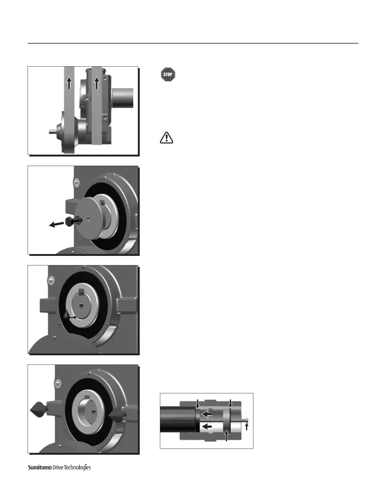
Externally support the Cyclo® HBB so that all the unit’s weight is removed from the
driven shaft.
The weight of the Cyclo® HBB must be externally supported throughout the
entire removal process.
Do not raise the unit too high! Shaft binding may occur.
2
Carefully remove the shaft-retaining device from the driven shaft.
3
Applyaliquidpenetranttotheshaftwhereitcontactsthekeyedhollowbore.
Allowtimefortheliquidtopenetratebetweentheshaftandthewallofthekeyed
hollow bore.
4
Once the penetrant has settled adequately, carefully remove the Cyclo® HBB from
the driven shaft.
Note: If shaft removal is difficult, a jig
such as the one shown here may be used
to ease the removal process. Sumitomo
Drive Technologies does not supply
the removal jig. This information is
supplied for reference only.
Internal Snap Ring
Spacer: Threaded and Keyed
Bolt
Thrust Disc

 Loading...


