Cyclo® HBB
Operation & Maintenance Manual 11
Cyclo® HBB
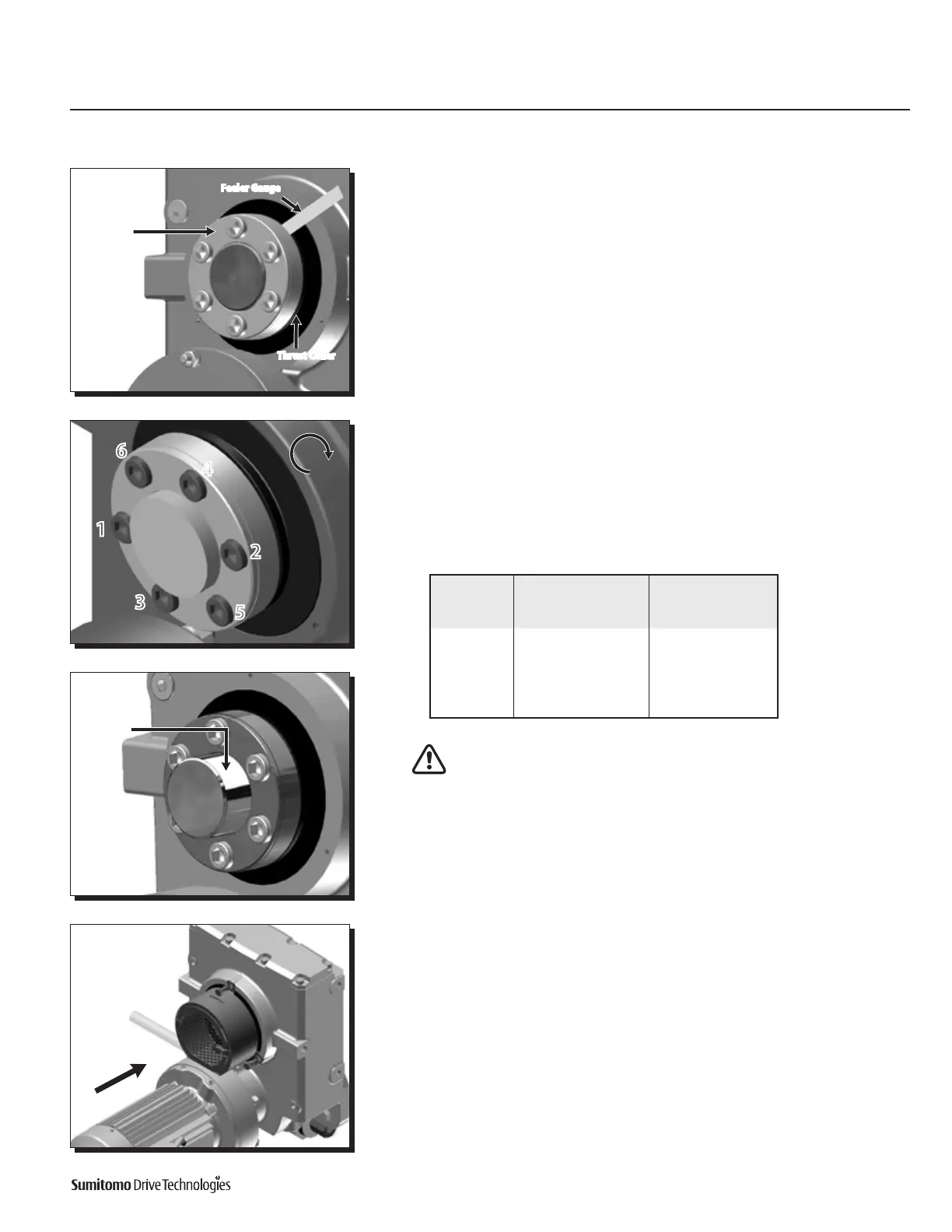
Installation onto Driven Shaft
Using Taper-Grip® Bushing
11
Screw bolts into Taper-Grip bushing.
• Lightlyoilthethreadsofeachboltbeforeinserting.
• Fingertighteneachbolttosecureinplace
• Besuretomaintain the 1 mm (approximate) gap between the thrust collar
and the bushing flange.
12
Tighten bushing bolts to the correct torque value.
• Followingastarpattern,useatorquewrenchtogradually tighten each socket
head cap screw in 20% increments.
• RefertoTable 1, Taper-Grip Bushing Bolt Tightening Torques, for the correct
operational screw torques.
After the reducer has been running for 20 to 30 hours, re-torque the screws
tothevaluesinTable2.Screwtorquesshouldbesubsequentlycheckedat
normal service intervals (i.e. every 6 months).
13
Apply grease to the exposed portion of the driven shaft.
• After installing and tightening the bushing bolts with a torque wrench, apply
grease or an anti-corrosion product to the exposed portion of the shaft.
14
For units that include a bushing safety cover, reinstall the guard over the
Taper-Grip® bushing.
Bushing
Flange
1-3mm
Feeler Gauge
Thrust Collar
1
6
4
2
5
3
Apply grease
to exposed
portion of
driven shaft.
Table 2. Taper-Grip® Bushing Bolt Tightening Torques
Cyclo® HBB
Model
Cap screws
(JISGrade12.9)
Cap screw
Torque
Qty. Size Nm Lb.Ft.
Z 6 M10x14 31 23
A 6 M12x16 51 37.5
B 6 M12x16 51 37.5
C 6 M16x20 128 95
D 6 M16x20 200 148
E 8 M16x20 200 148

 Loading...


