Operation & Maintenance Manual 5
Cyclo® HBB
Cyclo® HBB
Type Prefix
Horizontal H
Ve rtical V
AGMA class(Gearmotoronly)
Brake
GearmotororReducer Specification
Class Suffix
I A
II B
III C
Suffix
With BrakeB
No Brake–
AGMA Class
Brake
EVYM
Prefix
Special S
Standard
Type Prefix
ShaftMount (HollowShaft) Y
Flange (Keyed HollowBore) F
28BY1
Y
B6125
5
Cyclo® HBBproduct code (always “E”)
Output shaft orientation
Mounting style
Inputconnection
Modification (Special feature)
GearmotorHP
(1750rpm)
Framesize
Mounting position andoptional specification(as required)
Ratio
Shaft specification
Output ShaftOrientation
Mounting Style
Input Connection
Modification
Gearmotor HP
(applies only to
1750 RPM)
--
Nomenclature Example:
EVYM5–B6125YB–AVY5–53
E –Cyclo HelicalBuddybox B6125 –Frame Size
V –Vertical Y –InchShaft Specification
Y –Shaft Mount(HollowShaft) B –AGMA Class II
M –IntegralMotor AV –Adj.FrequencyMotor
5 –5HP, 1750 RPM Y5 –Installation Position
53 –Ratio
SpecificationSuffix
Three-PhaseMotor
Single-Phase Motor SG
AF Motor(Adj. Frequency) AV
Single-Phase Motor SG
ServoMotor SV
DC Motor DV
High Capacity Bearing
R1
(Required forScrew Conveyor)
Torque Limiter TL
Gearmotor Specification
Frame Size
Single Reduction
Z6090 B6120D6160
Z6095 B6125D6165
A6100 C6140E6170
A6105 C6145E6175
Double Reduction
Z609DAC614DBD616DC
A610DAC614DCE617DA
B612DA D616DA E617DB
B612DB D616DB E617DC
C614DA
Mounting Positions
Single
Reduction
Input Total
Ratio Ratio
3 11
5 18
6 21
8 28
11 39
13 46
15 53
17 60
21 74
25 88
29 102
35 123
43 151
51 179
59 207
71 249
87 305
119 417
Double
Reduction
Input Total
Ratio Ratio
104 364
121 424
143 501
165 578
195 683
231 809
273 956
319 1117
377 1320
473 1656
559 1957
649 2272
731 2559
841 2944
1003 3511
1247 4365
1479 5177
1849 6472
2065 7228
2537 8880
3045 10568
3481 12184
4437 15530
5133 17966
6177 21620
7569 26492
Nominal Total Ratio
Y1
Y2
Y3
Y4
Y5
Y6
Shaft Specifications
Input Connection
Gearmotor
Prefix
Reducer
Prefix
IntegralMotor M
C-Face Adapter JM J
Hollow InputShaft XM X
HP kW Prefix
1/8 0.1 01
1/4 0.2 02
1/3 0.25 03
1/2 0.4 05
3/4 0.55 08
1 0.75 1
11/2 1.1 1H
2 1.5 2
3 2.2 3
5 3.7 5
71/2 5.5 8
10 7.5 10
15 11 15
20 15 20
25 18.5 25
30 22 30
40 30 40
Input
Shaft
Hollow
Output Shaft
Suffix
mm Key(mm)
DIN Key(DIN) E
Inch Key(Inch) K
mm Taper-Grip® M
DIN Taper-Grip® G
Inch Taper-Grip® Y
Type Suffix
Standard
High Capacity Bearing R1
(Requiredfor ScrewConveyor)
Baseplate BP
Shovel Base SB
TopMount Center –
Right PR
Left PL
Low Backlash LB
Torque Limiter TL
ReducerSpecification
B
Type Prefix
Horizontal H
Ve rtical V
AGMA class(Gearmotoronly)
Brake
GearmotororReducer Specification
Class Suffix
I A
II B
III C
Suffix
With BrakeB
No Brake–
AGMA Class
Brake
EVYM
Prefix
Special S
Standard
Type Prefix
ShaftMount (HollowShaft) Y
Flange (Keyed HollowBore) F
28BY1
Y
B6125
5
Cyclo® HBBproduct code (always “E”)
Output shaft orientation
Mounting style
Inputconnection
Modification (Special feature)
GearmotorHP
(1750rpm)
Framesize
Mounting position andoptional specification(as required)
Ratio
Shaft specification
Output ShaftOrientation
Mounting Style
Input Connection
Modification
Gearmotor HP
(applies only to
1750 RPM)
--
Nomenclature Example:
EVYM5–B6125YB–AVY5–53
E –Cyclo HelicalBuddybox B6125 –Frame Size
V –Vertical Y –InchShaft Specification
Y –Shaft Mount(HollowShaft) B –AGMA Class II
M –IntegralMotor AV –Adj.FrequencyMotor
5 –5HP, 1750 RPM Y5 –Installation Position
53 –Ratio
SpecificationSuffix
Three-PhaseMotor
Single-Phase Motor SG
AF Motor(Adj. Frequency) AV
Single-Phase Motor SG
ServoMotor SV
DC Motor DV
High Capacity Bearing
R1
(Required forScrew Conveyor)
Torque Limiter TL
Gearmotor Specification
Frame Size
Single Reduction
Z6090 B6120D6160
Z6095 B6125D6165
A6100 C6140E6170
A6105 C6145E6175
Double Reduction
Z609DAC614DBD616DC
A610DAC614DCE617DA
B612DA D616DA E617DB
B612DB D616DB E617DC
C614DA
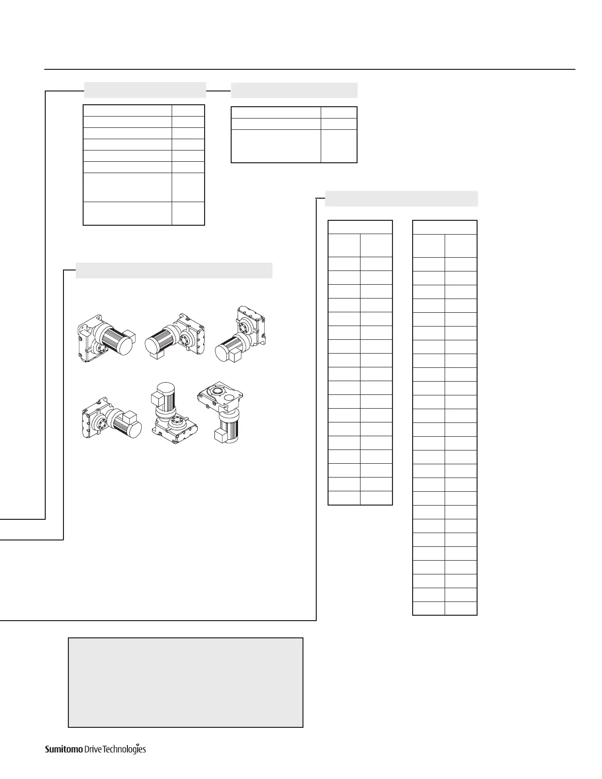
Mounting Positions
Single
Reduction
Input Total
Ratio Ratio
3 11
5 18
6 21
8 28
11 39
13 46
15 53
17 60
21 74
25 88
29 102
35 123
43 151
51 179
59 207
71 249
87 305
119 417
Double
Reduction
Input Total
Ratio Ratio
104 364
121 424
143 501
165 578
195 683
231 809
273 956
319 1117
377 1320
473 1656
559 1957
649 2272
731 2559
841 2944
1003 3511
1247 4365
1479 5177
1849 6472
2065 7228
2537 8880
3045 10568
3481 12184
4437 15530
5133 17966
6177 21620
7569 26492
Nominal Total Ratio
Y1
Y2
Y3
Y4
Y5
Y6
Shaft Specifications
Input Connection
Gearmotor
Prefix
Reducer
Prefix
IntegralMotor M
C-Face Adapter JM J
Hollow InputShaft XM X
HP kW Prefix
1/8 0.1 01
1/4 0.2 02
1/3 0.25 03
1/2 0.4 05
3/4 0.55 08
1 0.75 1
11/2 1.1 1H
2 1.5 2
3 2.2 3
5 3.7 5
71/2 5.5 8
10 7.5 10
15 11 15
20 15 20
25 18.5 25
30 22 30
40 30 40
Input
Shaft
Hollow
Output Shaft
Suffix
mm Key(mm)
DIN Key(DIN) E
Inch Key(Inch) K
mm Taper-Grip® M
DIN Taper-Grip® G
Inch Taper-Grip® Y
Type Suffix
Standard
High Capacity Bearing R1
(Requiredfor ScrewConveyor)
Baseplate BP
Shovel Base SB
TopMount Center –
Right PR
Left PL
Low Backlash LB
Torque Limiter TL
ReducerSpecification
B
Nomenclature, continued
Gearmotor Specification
Reducer Specification
Mounting Positions
Nomenclature Example:
EVYM5-B6125YB-AVY1-53
E - Cyclo® Helical Buddybox
V - Vertical
Y - Shaft Mount (Hollow Shaft)
M - Integral Motor
5 - 5 HP (3.7kW), 1750 RPM
B6125 - Frame Size
Y - Inch Shaft Specification
B - AGMA Class II
AV - Adj. Frequency Motor
Y5 - Installation Position
53 - Ratio
Specification Suffix
Three-Phase Motor
Single-Phase Motor SG
AF Motor (Adj. Frequency) AV
Servo Motor SV
DC Motor DV
High Capacity Bearing
(RequiredforScrew
Conveyor)
R1
Premium Efficient
Three-Phase Motor
EP
Type Suffix
Standard
High Capacity Bearing
(RequiredforScrew
Conveyor)
BP
Nominal Total Ratio
Single Reduction
Input
Ratio
Total
Ratio
3 11
5 18
6 21
8 28
11 39
13 46
15 53
17 60
21 74
25 88
29 102
35 123
43 151
51 179
59 207
71 249
87 305
119 417
Single Reduction
Input
Ratio
Total
Ratio
104 364
121 424
143 501
165 578
195 683
231 809
273 956
319 1117
377 1320
473 1656
559 1957
649 2272
731 2559
841 2944
1003 3511
1247 4365
1479 5177
1849 6472
2065 7228
2537 8880
3045 10568
3481 12184
4437 15530
5133 17966
6177 21620
7569 26492

 Loading...


