4.1
Platform Layout
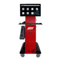
This section provides details of the Diagnostic Platform general layout.
4.2
Gas Module Layout
4.2.1
Gas Module Layout - SGMII
Figure 4-2 The Gas Module - Side & Bottom Panels
1.
USB connection for PC interface
2.
Power LED indicator
3.
12vDC power input jack
4. O2 Sensor (p/n 7096E4060-31)
5.
Clean air inlet (with charcoal filter (p/n 7096E9061-54) to filter
incoming air)
6.
Water Bowl (p/n 1-41780A)