User Manual 5 Electrical Connection
31
To avoid the
input power unbalance of the two inputs or input
load-restriction, ensure the two PV input cables are of the same type.
5.4.2 Assembling the PV Connector
All PV cables are equipped with the water-proof direct plug-in connectors which
match the PV terminals at the bottom of the inverter.
The PV cables must be multi-stranded wires.
To ensure the protection degree IP65, only use the connectors
delivered or connectors with the same degree of protection.
The requirements of PV cables are as follows.
4 mm
2
–6 mm
2
6 mm–9 mm 600 V
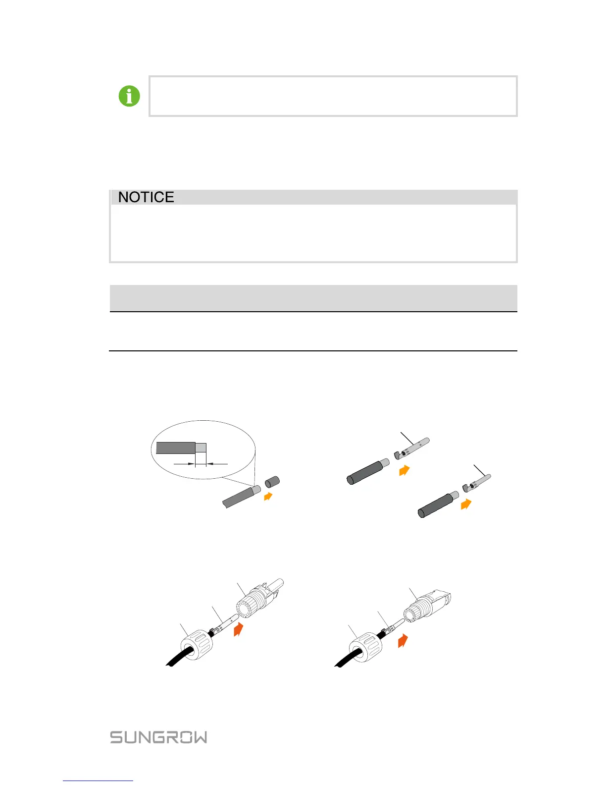
1. Strip the insulation from the cables
2. Assemble the cable ends
Positive Crimp Contact
Negative Crimp Contact
3. Lead the cable through cable gland, and insert into the insulator until it
snaps into place. Then tighten the cable gland (torque 2.5 Nm to 3
Nm).
Crimp Contact
Positive Insulator
Cable Gland
Crimp Contact
Negative Insulator
Cable Gland
4. Make sure that the cable polarity of each PV string is correct before
connecting it to the inverter.



 To Next Page