5 Electrical Connection User Manual
34
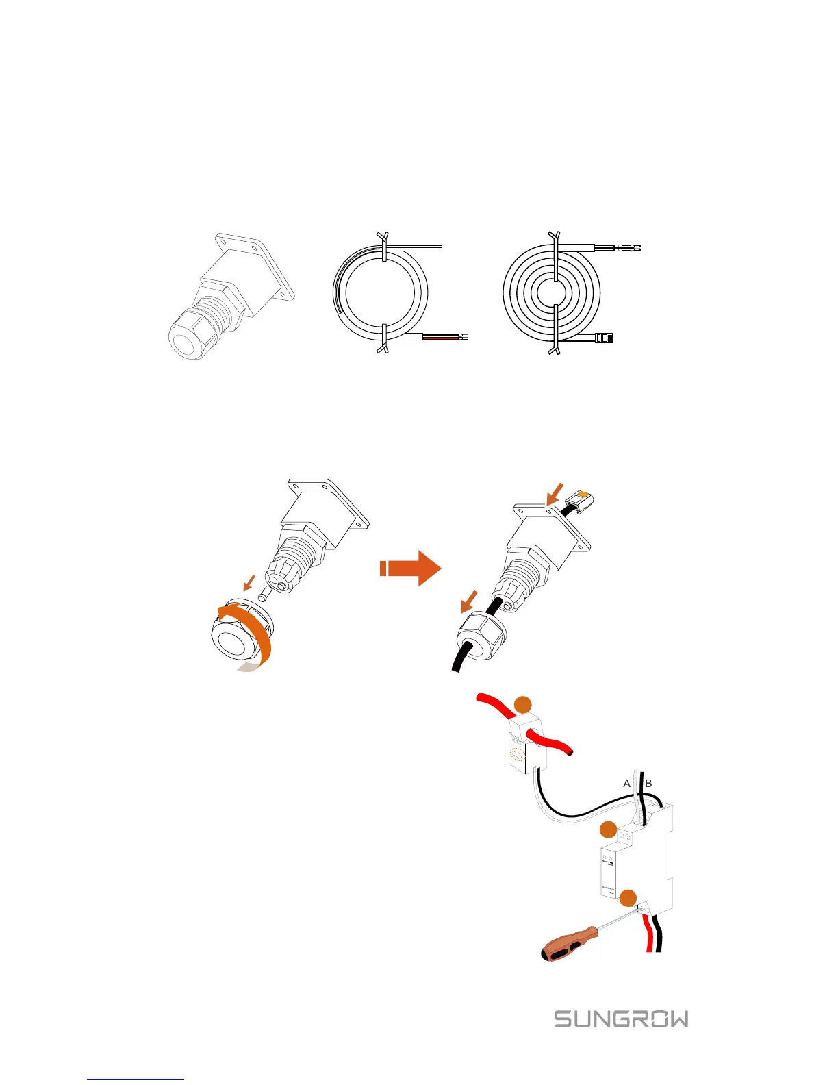
5.6.1 On the Meter Side
For Single-phase Energy Meter
1. Take out the communication connector from inverter’s packaging, and
the meter (with 1-phase sensor) and cables from the meter’s packaging.
L
N
B
A
Power supply cable Meter RS485 cable
Communication connector
2. Unscrew the swivel nut from the cable gland and remove the waterproof
plug from the left inlet. Lead the A and B plugs from inside out through
the connector. This will result in the cable with the RJ45 plug on the
inside end, and the A and B plugs on the outside.
3. Connect the cables to the meter.
wires to terminal 3 (L) and
terminal 6 (N).
−
(b) Tighten the RS485 wires to
terminal 2 and terminal 5.
− (c) Place the 1-phase sensor
around the phase wire (L
the main switch.
The CT clamp of 1-phase sensor
can be placed before or after the
main switch.



 To Next Page