User Manual 5 Electrical Connection
35
Make sure that the CT clamp of 1-phase sensor is installed in the right
direction: the arrow on the sensor must point away from the grid
towards the load.
For Three-phase Energy Meter
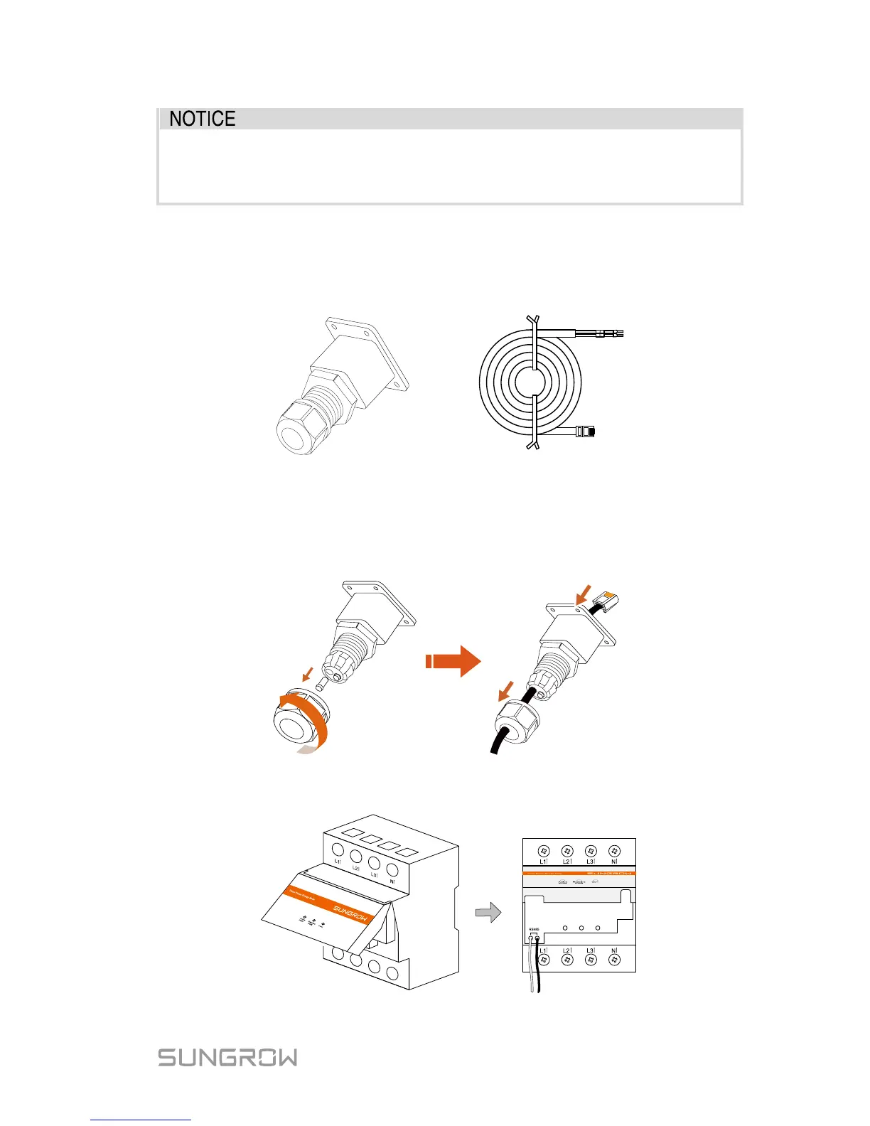
1. Take out the communication connector from inverter’s packaging, and
the meter and RS485 cable from the meter’s packaging.
B
A
Meter RS485 cableCommunication connector
2. Unscrew the swivel nut from the cable gland and remove the waterproof
plug from the left inlet. Lead the A and B plugs from inside out through
the communication connector. This will result in the cable with the RJ45
plug on the inside end, and the A and B plugs on the outside.
3. Connect the A and B plugs to terminals A and B on the Energy Meter, as
shown below.
 Loading...