7 LCD Operation User Manual
46
Tab. 7-4 Default Parameters for Grid Standards
Parameter
10-Minute Over-voltage Protection
ON: enables the protection function by default. The
inverter will automatically disconnect from the grid
within 3 s when the average voltage for a 10 min
period exceeds the set-point of 10 Min Over Vtg.
OFF: disables the function.
Range: 244.0 V–258.0 V
The default value of 10 Min Vtg is 248.0 V for New Zealand (code “NZ”). Refer
to the following table for different grid standards in Australia.
Parameter
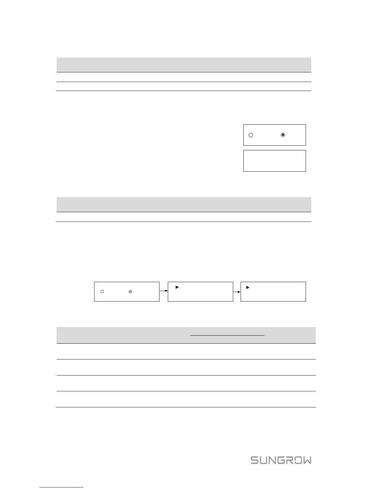
Volt-watt Response
The Volt-watt response mode is enabled by default.
Set four grid voltage reference values. The output power of the inverter will vary
in response to the grid voltages.
OFF ON
V1 Ref.: 207.0V
V2 Ref.: 220.0V
V4 Ref.: 265.0V
V3 Ref.: 250.0V
Tab. 7-5 “Volt-watt” Mode Parameter Explanations
Parameter Explanation
Grid voltage reference
value 1
Grid voltage reference
value 2
220.0 V 220.0 V 216 V–230 V
V3 Ref.
Grid voltage reference
value 3
250.0 V 244.0 V 235 V–255 V
V4 Ref.
Grid voltage reference
value 4
265.0 V 255.0 V 244 V–265 V
The response curve is defined by the voltage reference values and
corresponding power levels.



 To Next Page