18
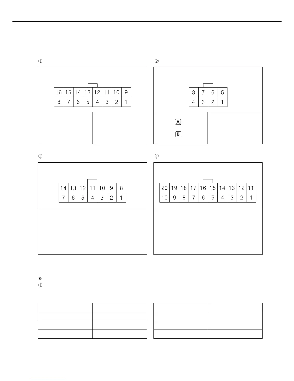
3) Names and Explanation of external connector in control box
[ Pin Number ]
[ Pin Number ] [ Pin Number ]
[ Pin Number ]
5,13: Left needle control
solenoid
6,14: Right needle control
solenoid
7,15: Thread release solenoid
8,16: Auxiliary solenoid
1, 9: Back Tack solenoid
2,10: knee lifter solenoid
3,11: Trimming solenoid
4,12: Wiper solenoid
1,5: Manual Back tack
button
2,6: Back tack Insert/Delete
Button
3,7: Knee lifter solenoid switch
4,8: Safety Switch
Solenoid Connector (5566-16P) Basic switch connector (5566-8P)
Switch and lamp connector (5566-14P) Extension connector (5566-20P)
4) Changing solenoid supply voltage (Basic setting values upon shipment: J19)
It is for a good operation of solenoid when AC input voltage changes.
Setting values of solenoid supply voltage against input voltage (input voltage 220V series)
Solenoid with the rating current of 30V Solenoid with the rating current of 24V
Input Voltage Setting Values
Less than 210V J20
210V~230V J19
More than 230V J18
Input Voltage Setting Values
Less than 180V J20
180V~190V J19
More than 190V J18
1, 2, 9, 10 : 12[V] 13 : Output 12
3~8 : GND 14 : Output 13
11, 12, 19, 20 : VCC (5[V]) 15 : Output 14
13~18: Extension Port 16 : Output 15
17 : External Input 00
18 : External Input 01
1, 2, 7 : GND 9 : 4/4
3 : Left switch LED 10 : 3/4
4 : Right switch LED 11 : 2/4
5 : Left switch 12 : 1/4
6 : Right switch 13 : Switch-CNT
8 : VCC (5[V]) 14 : Switch-HALF
 Loading...